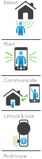
The receiving device within the proximity of a door has a sensor to detect approaching individuals and cause an action to occur within the system.
See patent - 7193644, claim (1)
This extensive portfolio governs 2-way audio video communication, sensing individuals, door locking and unlocking and much more. Opportunites being offered in regard to this porfolio are available upon request. Please contact us to further examine the opportunities this significant patent porfolio may provide for your market.
Read the entire patent portfolio!

The patent portfolio consists of one awarded utility patent, two awarded continuation patents, three awarded continuation-in-part patents and one pending continuation-in-part patent.
This extensive patent portfolio patents the process of utilizing 2-way audio video communication by a device with a camera, microphone and video screen in the proximity of a door transmitting to one or more wireless devices such as a mobile phone or tablet inside the home or at another remote location.
Additional methods protected by this portfolio are the sensing of an approaching individual and alerting a second individual via a wireless device, playing pre-recorded announcements to an individual at the location of a receiving device, the locking and unlocking of a door remotely via a wireless device, the monitoring and surveillance of an entrance area via a wireless device, plus additional process and methods as described in the patents.
This portfolio is extraordinary in both the scope of applications and the industries in which they are applicable.
EyeTalk is an IT development company and systems provider focused on the design and development of wireless communication and security application technologies. The company's patent portfolio offers intuitive and independent capabilities and utilizes a platform that interfaces seamlessly with smart devices such as iPhone, iPad, Windows, Blackberry and Andriod in addition to various cameras and monitoring devices. The wireless wave is driving technology and these patents represent the future in wireless security and communications. These patents are essential and effective in a variety of applications. The company holds patented and patent pending applications that utilize smart camera technology in entryway management and security applications.

Companies looking to benefit from the advantages that this patent portfolio enjoys in the marketplace are directed to contact Mr. Helfer, Managing Partner for technology licensing, at 980-819-0435 . The broad applications and diverse industries in which these patents apply offer significant opportunities. We can help you further examine this extensive porfolio and it's applicability for your company's current and future products and the industries in which they apply. This portfolio could truly position your company as a leader in the wireless security and communications marketplace.
The receiving device within the proximity of a door has a sensor to detect approaching individuals and cause an action to occur within the system.
See patent - 7193644, claim (1)
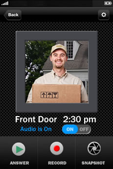
Enables a person to be alerted on their mobile device that an individual is at their door and initiate an audio and video conversation via their mobile device with the person at their door regardless if they are at home, across town or away on vacation. You can even watch and listen to the individual before electing to respond live or play an automated message.
See patent - 8144183, claim (1,2,9,10,11,12,15,16) &
8139098, claims (1,3,5,13,14,15,16,17)
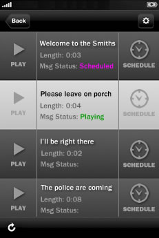
The device at the door can greet an individual with a pre-recorded message. Additionally the individual can be prompted to respond to a request for keypad input resulting in selected pre-recorded messages or selected individuals alerted on their mobile devices to respond.
See patent - 8139098, claims (7,8,9,10,11,12)
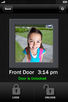
Enables greeting a person on your phone while you are at home or away, visually confirming their identification and then allowing entrance by remotely unlocking the door. A great solution for confirming safe entrance for kids to home while you are away and securing the home once they are inside by locking the door remotely.
See patent - 7193644, claim (15).
The device at the door can initiate an alert to a mobile device upon sensing an individual and begin streaming a confidential live video of the area by the door. Video stream can also be joined by connected devices for larger area coverage.
See patent - 8139098, claim (1,5).
Enables a person to be alerted on their mobile device home or facility has lost land lines or power supplied from utility companies.
See patent - 7193644, claim (24).
The device at the door can initiate various operations following identification via keypad input, voice prompt, or fingerprint or retina biometrics. Once an individual is id, remote individuals may be wirelessly alerted, specific system messaging may be played and door unlocking can result.
See patent - 7193644, claims (1,) & patent 8144184, claim (17).
The system can be set to record area video and audio continuously or after sensing an individual and then archive it on various media for later viewing.
See patent - 8139098, claims (2,4,5).
Enables solutions that can alert a single user on thier mobile device or multiple individuals simultaneously. Which individuals are alerted on their mobile systems can be determined via keypad, voice prompt or biometric identification.
See patent - 8164614, claims (1,6,7,8,9,10,11,12,13,20).
Enables the primary device to be quickly located virtually anywhere. Because device can transmit wirelessly, be battery powered and also has a locking mechanism that enables it to be secured in place it can be used in a numerous places where without the difficulty of typical installation issues.
See patent - 8154581, claims (13,14).
The primary device's camera can possess additional capabilities such as actuation for pan of viewing area from remote wireless phone or tablet. System can also be zoom enabled allowing for remote user to zoom in on area being viewed.
See patent - 8139098, claim (18,19).
The primary device located near a door may possess a video screen that enables 2 way audio video communication between the participants. Additionally the video screen can be used for informational and on-site marketing videos and disclosures. Such videos can prompt user for action resulting in an alert to a remote user and then both parties being engaged in a live 2-way audio video conversation.
See patent -8144183, claim (1,2,9,10,11,12,15,16) & 8154581, claim (11).
"Initial patent establishing, amongst other claims, a 2-way audio video communication in the proximaty of a door to a remote wireless device. System also has remote locking and unlocking of door and sensing of approaching individuals"
"Continuation-in-part of 7,193,644. Amongst other claims, defines remotely actuating the camera at the entrance including zooming and timestamping video when archiving."
"Continuation-in-part of 7,193,644. Amongst other claims, defines exterior module located by door may also be wireless."
"Continuation of 7,193,644. Amongst other claims, defines biometric identification of an individual for authentication."
"Continuation-in-part of 7,193,644. Amongst other claims, defines person received at entrance being able to see video in addition to audio of second person on remote mobile device."
"Continuation of 7,193,644. Amongst other claims, defines a plurality of peripheral devices connected via the internet used in applications together."
Ross Helfer
Managing Partner
rhelfer@eDev3.com
980-819-0435
EyeTalk365
9923 Willow Leaf Ln.
Cornelius NC 28031
Please contact us to further examine the opportunities this significant patent porfolio may provide for your market.
FRONT
| Publication type | Grant |
| Application number | 10/682,185 |
| Publication date | Mar 20, 2007 |
| Filing date | Oct 9, 2003 |
| Priority date | Oct 15, 2002 |
| Also published as | |
| Inventors | |
| Original Assignee | |
| U.S. Classification | |
| International Classification | |
| Cooperative Classification | |
| European Classification | H04N7/14A3
H04N7/14A2
|
| References | |
| External Links |
DRAWINGS (5)


ABSTRACT
The invention is an audio-video communication and answering system that synergistically improves communication between an exterior and an interior of a business or residence and a remote location, enables messages to be stored and accessed from both locally and remotely, and enables viewing, listening, and recording from a remote location. The system's properties make it particularly suitable as a sophisticated door answering-messaging system. The system has a DVMS module on the exterior. The DVMS module has a proximity sensor, a video camera, a microphone, a speaker, an RF transmitter, and an RF receiver. The system also has a computerized controller with a graphic user interface DVMS database application. The computerized controller is in communication with a public switching telephone network, and an RF switching device. The RF switching device enables communication between the DVMS module and the computerized controller. The RF switching device can be in communication with other RF devices, such as a cell phone, PDA, or computer.
DESCRIPTION
CROSS REFERENCE TO RELATED APPLICATION
This application claims the benefit of U.S. Provisional Application No. 60/418,384, filed on Oct. 15, 2002.
FIELD OF THE INVENTION
The present invention is generally a system for monitoring and interacting with a visitor at a residence or business, and more particularly a system for detecting the presence of a visitor, interactively communicating therewith at a heightened level of security, enabling automated entry, and generally enhancing and personalizing the overall process of receiving a visitor. The system utilizes new technology to synergistically improve messaging, communication, security and create time saving advantages for both the visitor and the provider of the system.
BACKGROUND OF THE INVENTION
There are numerous problems presently associated with receiving visitors at a home or office. When the resident is absent, there is often no message for the visitors, no means to leave an interactive message for the resident, and no means to ensure that unwanted access is not obtained. Moreover, answering the call of someone at a door of a dwelling can present certain security risks to an occupant therein. This situation can be especially inconvenient when, for example, a delivery or repair person arrives and the resident is not present. When the resident is present, on the other hand, there are also problems associated with receiving visitors. Some visitors may be unwelcome, for example, and it is often not evident that a visitor is a threat or an annoyance until after the door is open and it is too late. In the past, there have been many intercom-type doorbell systems which enable a person to speak to a visitor at the front door before opening it. None of these intercom-type devices, however, has stored messaging that makes them useful when the resident is away from home or unavailable. Moreover, none of these systems has communication capabilities with remote devices. Thus, they neglect to address many of the problems associated with receiving visitors.
U.S. Pat. No. 5,148,468 "Door answering system", which issued Sep. 15, 1992 to Marrick et al, discloses a door messaging system that records messages from visitors. This device, however, has no intercom capability for permitting the resident to speak with the visitor, nor does it have a screening capability whereby the resident can secretly monitor a message as it is being left by a visitor. Another disadvantage of this device is that, like many telephone messaging systems, its interaction with the owner is not intuitive or hands free, and its interaction with the visitor is limited to a single option. In addition, it is tape-based, therefore less robust, and less versatile than digital systems, and it requires custom wiring between the interior and exterior units.
U.S. Pat. No. 5,303,300 "Security door phone device", which issued Apr. 12, 1994 to Eckstein, discloses a device that calls a predetermined telephone when a visitor arrives at their door, thereby allowing residents to converse with the visitor via telephone, or allows their telephone answering machine take a message. The answering machine can also be used to screen visitors just as answering machines are often used to screen telephone calls. This device, however, has several disadvantages. Because the system relies upon a telephone for the intercom feature, it does not permit the resident to converse with the visitor while the telephone is in use. In addition, because the telephone answering machine is used for both telephone and visitor messaging, if the telephone is in use when a visitor arrives, then the visitor cannot leave a message and the resident can not screen the visitor. Moreover, since the same machine is used for both phone and door answering, the two types of messages can become easily confused. This system is also not self-contained since the messaging feature can only be performed in combination with a telephone and a telephone answering machine. This complication also increases the likelihood that the system will malfunction. Additional disadvantages are that this system has, like most telephone answering machines, a primitive messaging system, it lacks interactivity, and it requires custom wiring between the interior and exterior units. Most phone messaging devices have little or no automated interactivity with the caller or the resident, and have no video capabilities. The flexibility of their interaction is limited since only one message is played to a caller and only one option is given to the caller (i.e., to record a message or not). Although the resident has more interactivity with the device through the use of several buttons corresponding to different functions, such interaction is not intuitive and often has peculiarities that vary from one machine to the next.
In recent years, certain consumer devices have appeared that use speech synthesis or speech recognition to enhance interactivity with the user. For example, U.S. Pat. No. 5,406,618 "Voice activated, hands free telephone answering device" issued Apr. 11, 1995 to Knuth, et al. discloses a telephone answering device that is activated by a proximity sensor and whose operation is controlled by simple voice commands by the resident. The device incorporates voice recognition circuitry to respond to spoken commands of the user that are elicited by a system generated voice request menu. The telephone-answering device performs all the basic functions of a telephone answering machine in response to these simple commands and there is no need for the user to manually operate the telephone-answering device. This telephone-answering device, however, is not designed for or capable of addressing the need for a door messaging and intercom system. Indeed, even if it were used in combination with the telephone intercom device of Eckstein, it still has serious deficiencies with the intercom and messaging features due to its reliance on the telephone connection. Moreover, such a combination only enhances the interactivity of the resident with the machine, and does not enhance the interactivity of the visitor with the machine. The visitor is still faced with a primitive messaging system with no interactivity. No prior art messaging system has flexible and intuitive interactivity with the visitor or caller.
U.S. Pat. No. 5,657,380 is an "Interactive door answering and messaging device with speech synthesis" that issued to Mozer on Aug. 12, 1997. Mozer discloses an automatic door answering and message system. The system comprises an interior unit and an exterior unit that communicate via an RF Link. Further, the system uses voice recognition to interact with visitors. The system fails to provide a user with the option of communicating through a variety of peripheral devices. Moreover, the system fails to provide a centralized control system having a user friendly application that coordinates the various communication scenarios commonly availed to a modem user, who has access to an array of remote peripheral communication devices (i.e., cell phone, video phones, hand-held computers, PDA's, etc.). The Mozer system also does not provide a means to handle the mundane day-to-day interaction with visitors who have a wide range of technological sophistication. Furthermore, the Mozer system is not intuitive and does not employ both video and audio technology to synergistically personalize messaging and communication, while improving security. Still further, the system fails to provide a security alarm option, which signals a predetermined address of a security breach.
There remains a need, therefore, for a self-contained door communication and messaging device that has simple and intuitive interactivity with the visitor, that has messaging capability permitting incoming and outgoing messages to be easily recorded and played, that permits the resident to screen visitors, that permits the resident to speak with visitors without opening the door, that does not require wiring from the exterior to the interior, that provides a centralized control system utilizing a user-friendly application, that provides a means for storing digital images, that provides enhanced security features, that is relatively inexpensive, and that is easy to install.
SUMMARY OF THE INVENTION
The invention is an audio-video communication and answering system that synergistically improves communication between an exterior and an interior of a business or residence and a remote location, communication between two or more rooms and a remote location, leaving messages at a centralized location from a local or remote location, and as a novel monitoring system for viewing, listening, and recording from a remote location. As will become obvious from the description, the system is inherently extensible in both form and function, and is designed so that it can be expanded to include multiple peripheral devices, both in direct communication with a computerized controller running a graphic user interface DVMS database application, and indirectly through the Internet and the public-switching telephone network (PSTN). Peripheral devices that are in direct contact with the computerized controller via a radio frequency (RF) link are designated as a DVMS device, as they communicate via short-range RF waves that have a direct view, and these peripheral devices are used to receive and convey messages to the other similar peripheral devices, as well as the computerized controller. Remote peripheral devices generally are in communication via established institutional channels, such as the Internet, satellite systems, PSTN, cell systems, cable systems, and to a lesser extent, long-wave length systems. Remote peripheral devices are selected from the group consisting of cell phones, telephones, video-cell phones, computers, personal digital assistants, video-personal digital assistants, satellite telephones, transceivers, pagers, and other analog or digital communication devices.
The centralized controller can be augmented with various switching devices to expand and control the peripherals. Many of the disclosed peripherals are commonly housed in a personal computer. Newer PC systems typically come with a variety of stock audio-video peripherals such as a video camera and DVD read/write devices, communication devices such as telephone/fax ports, networking ports for hard-wired and wireless LANs, and come with large amounts of fast access memory, such as hard drives, CD-ROM read/write, and RAM. These peripherals are off-the-shelf, and are suitable for the disclosed system. The disclosed system can be configured to accommodate audio-video communication and answering applications having a range of complexity.
The basic system is comprised of: a DVMS module, having a proximity sensor, a video camera, a microphone, a speaker, an RF transmitter, an RF receiver, and a keypad; a computerized controller with a graphic user interface DVMS database application, wherein the computerized controller is in communication with a public switching telephone network; an RF switching device, wherein the RF switching device enables communication between the DVMS module and the computerized controller and, depending on how the system is configured, the RF switching device is in communication with other RF devices; a recording means for recording video and audio communication that is transmitted to and from the DVMS module; a playing means for playing video and audio communication stored on the recording means, or other storage devices having rapidly accessible data; a speaker; and a remote peripheral device. The DVMS database application coordinates the multiple communication devices, and it is used to define responses to prompts and events.
The DVMS module preferably also has a display screen that is a LCD screen. The keypad can be a LCD touch screen or a keyboard. The DVMS module is portable, and has a locking mechanism for fastening it to a holster. The DVMS module has an electrical receptacle that enables it to be quickly attached to an electrical source.
A desired additional peripheral for the audio-video communication and answering system is a DVMS transceiver having a display screen, a microphone, a speaker, a limited range RF transmitter, a RF receiver, and a keypad. As previously mentioned, a DVMS peripheral device communicates directly with the computerized controller.
The display screen on the DVMS transceiver and the DVMS module preferably has a low energy screen like a LCD screen, which is an advantageous feature, in that besides reducing energy consumption, it enables text messaging. Text messaging allows one to communicate with a visitor privately.
In systems that are principally going to be used to control access to the premises, then the system also includes an electronically actuated lock, which can be unlocked by the computerized controller.
It is anticipated that in certain deployments of the invention that voice recognition would be useful, particularly when the system enables access to the premises. Voice recognition adds another layer of security, and can be used to facilitate those individuals who are unable to press a keypad. Similarly, as the base system records video image recognition of faces, eyes and fingerprints can also be included in the system.
Commonly, prompts are generated either as a stored audio message or by voice synthesis. The audio-video communication and answering system can use either mechanism to generate the prompts, and the system can be configured accordingly. Voice synthesis is slightly faster and more reliable and has recognized advantages at a small incremental cost.
The computerized controller of the audio-video communication and answering system preferably has a battery backup, and a means for detecting a loss in electrical power. Thereby, when power is lost there will be sufficient time to notify those responsible for the maintenance of the system that there has been a loss of electricity. There are a couple of reasons that make this a particularly important feature. If there is no power, then it is possible that there has been a break in. In addition, if there is no power then other appliance, such as refrigerators, air conditioners, and heaters cannot function, and when they do not work, significant damage often results when their failure goes undetected for a sustained period of time.
The database application is administered by the administrator, who defines the users, who in the case of the instant invention are called occupants, reflecting their status on the premises. The occupants have various levels of access to the database, depending on the privileges set by the administrator. Other examples of settings determined by the administrator are aliases for a declared occupant, whom may also be known as (i.e., "Daddy" or "Momma"), passwords to access the database; access codes to actuate a lock, a number that corresponds to an occupant's name, and at least one telephone number where an occupant can be reached. Voice, text, and video messages may also be sent via email, and the administrator can set up redundant systems. Further, the administrator can use default prompts for interacting with a visitor, or he can create his own. The administrator chooses a prompt for greeting a visitor; an announcement that is to be given over the speaker when a visitor arrives; a prompt for requesting information from a visitor; a request instructing a visitor as to their choices in leaving a message or contacting a declared user; and the action that is to be initiated by the system based on the input by the visitor. The invention can be configured to play background music or videos at different times of the year, and/or different times of the day to reflect seasonal holidays, birthdays, and events. For instance, on Halloween the administrator may wish to have scary music and howls issuing from the DVMS module. The administrator can tailor the security/premise monitoring response to designate the telephone numbers that are to be called when there is a loss of power; emergency numbers that are to be automatically called (i.e., the police, the fire department, relatives, private security companies), and a log of self checks to confirm that all the components of the system are operational. Also, depending on the size of the system the administrator may wish to set the level of security that the system is to operate under, particularly with respect to via the dedicated digital communication channel (i.e., the Internet and the Grid). As hardware is added, such as the number of the DVMS modules and DVMS transceivers, the network should be updated. Also, the administrator can define the preferred hierarchy of storage of audio and video data, the location and number of backup devices, and whether replications of the database are to be kept.
In view of the foregoing disadvantages inherent in the known types of audio-video communication and answering systems now present in the prior art, the present invention provides an improved system. As such, the general purpose of the present invention, which will be described, subsequently, in greater detail is to provide a new and improved system, which has the advantages of the prior art and none of the disadvantages.
In this respect, before explaining at least one embodiment of the invention in detail, it is to be understood that the invention is not limited in its application to the detailed construction and to the arrangements of the components set forth in the following description illustrated in the drawings. The invention is capable of other embodiments and of being practiced and carried out in various ways. Also, it is to be understood that the phraseology and terminology employed herein are for the purpose of the description and should not be regarded as limiting.
The invention is a method for audio-video greeting and communicating with visitors of a business or residence. The method is comprised of detecting the presence of a visitor via the proximity sensor of the DVMS module, where the DVMS module is mounted at or near an entrance to the business or residence, wherein upon detection the computerized controller is signaled that a visitor is present. The recording means is actuated, and the recording is stored in the database along with a beginning time-stamp. The arrival of a visitor is broadcast over a speaker within the premises. An occupant can view the visitor on the DVMS transceiver or on the computerized controller display monitor, and initiate a conversation at any time. The DVMS module issues a greeting to the visitor, and instructs the visitor to select a number from the keypad, which designates whom they wish to visit. The entered number is transmitting from the DVMS module to the GUI database application, where the application confirms that the number corresponds to an occupant "y", who is "officially" present. An error message is generated if no individual corresponds to the number entered. While this is going on, the door may be answered at any time, thereby resetting the application to look for another visitor. The application keeps track of the number of times a wrong number is entered and can generate a variety of responses to pranks, including calling the police, issuing warnings and/or a loud noise, or just thanking the visitor and asking him to return another time. If no one corresponds to the number, the visitor is prompted to select and press another number on the keypad, designating whom he or she wish to visit. The method then re-lists the choices. If appropriate, when the number matches an occupant who is on the premises, the speaker broadcasts that the visitor is here to see occupant "y". Occupant "y" can signal the computerized controller to take a message, or occupant "y" may choose to use the DVMS transceiver to speak directly with the visitor, or occupant "y" can answer the door. If appropriate, the DVMS module issues a prompt stating that occupant "y" is not available and asks the visitor if they wish to speak to occupant "y" or to leave a message. If appropriate, at any time the application can initiate a call to occupant "y", and record both sides of the conversation. The occupant can only view the visitor, or initiate a conversation. When a call is made to any remote peripheral device, the dial tones are muted so that a visitor cannot record the tones. A visitor never knows where the occupant is, unless the occupant tells the visitor. A visitor never knows if the occupant can be contacted, or if the occupant has just instructed the application to take a message. If the visitor has elected to leave a message then the method prompts the visitor to begin his message and then, optionally, offers him a chance to review and approve his message. The message or call is stored in the database with a beginning timestamp and an ending timestamp, along with the occupant's mailbox number. At the end of the call or message, the application can issue a closing statement and return to background music, if programmed to do so. When the visitor departs, and is out of the range of the proximity sensor all recording is stopped and saved in the database record, along with an ending timestamp. The occupant "y" can selectively sort to view the entire recorded visit, or just the message. If the proximity sensor indicates that there is another visitor, the method cycles back to the greeting step.
Using the method the conversation or messages can be relayed to the selected occupant, without the visitor ever knowing where the occupant is. Only the occupant can disclose his location to the visitor.
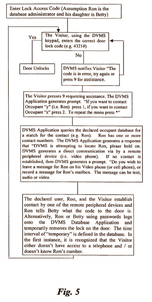
If the system has an electronically actuated lock, then the method can also be comprised of the steps of checking the number entered by the visitor to determine if it is a valid access code. If the number is valid then actuating the lock, and if the number is not valid, prompting the visitor to re-enter the code, or if assistance is needed to enter a number that corresponds to one of the occupants. If an occupant is selected, calling the selected occupant. The occupant has the option of remotely entering the access code, therein actuating the electronically actuated lock, or instructing the GUI database application to go to a new high security level, wherein the lock cannot be accessed and notifying the visitor that the access code is not operational. If the visitor enters an access code, checking the code, and tracking how many times the wrong code is entered. Checking the database application if the maximum allowed number of wrong entries have been made. When the maximum number of entries is reached, either automatically calling a designated party and/or removing access privileges. Looping back to the first step.
In the method, upon the entering of a valid access code assigned to a declared occupant, the application optionally notifies the administrator or his designated representative that the declared occupant has now entered the premises of the business or residence. (The administrator would know who the individual should be. The administrator can confirm, by remotely viewing the recorded video, that the actual person who entered the access code is the declared occupant, and/or make a follow-up telephone call to the premises.
As such, those skilled in the art will appreciate that the conception, upon which the disclosure is based, may readily be utilized as a basis for the designing of other structures, methods, and systems for carrying out the several purposes of the present invention. It is important, therefore, that the claims be regarded as including such equivalent constructions in so far as they do not depart form the spirit and scope of the present invention.
OBJECTS OF THE INVENTION
The principal object of the present invention is to provide an audio-video communication and answering system that can be used as a door answering system.
A further object of the present invention is to provide an improved door answering system which provides the option of having a visitor converse with an occupant, leave a message, or contact a remote device for communication with the occupant.
A still further object of the present invention is to provide an audio-video communication and answering system, which upon sensing that a visitor is proximate, to digitally record the visitor. The recording can be viewed in real time, or at a later time, either locally or remotely.
A still further object of the present invention is to provide an audio-video communication and answering system that is simple to operate by both the occupant and the visitor.
A still further object of the present invention is to provide an improved door answering system which activates an alarm and or initiates calls to designated institutions and individuals when there is a security breach.
A still further object of the present invention is to provide an improved door answering system which allows the administrator or his designated representative to remotely permit entrance to a building by visitors.
A still further object of the present invention is to provide an audio-video greeting and communicating system that can be tailored to reflect holidays, special occasions, and various levels of security.
Another object of the present invention is to provide an audio-video greeting and communicating system that can be configured to contact the administrator or his designated representatives that when there is a loss of electrical power.
These together with other objects of the present invention, along with various features of novelty, which characterize the invention, are pointed out with particularity in the claims and form part of the disclosure. For better understanding of the invention, its operating advantages, and the specific objects obtained by its uses, reference to the accompanying drawings and descriptive manner should be made, which are illustrated of preferred embodiments of this invention.
BRIEF DESCRIPTION OF THE DRAWINGS
A full and enabling disclosure of the present invention, including the best mode thereof, to one of ordinary skill in the art, is set forth more particularly in the remainder of the specification, including reference to the accompanying drawings in which:
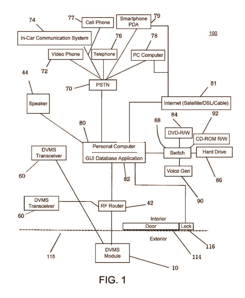
FIG. 1 is a schematic diagram of the illustrated embodiment of the present invention.
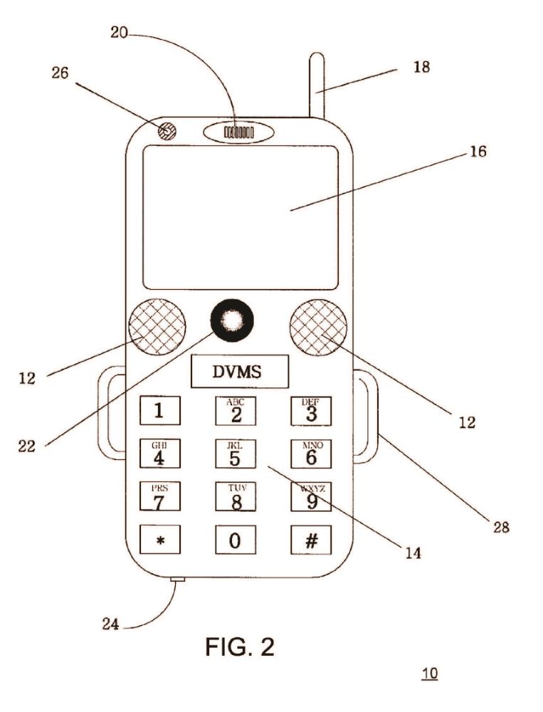
FIG. 2 is a planar view of the DVMS module.
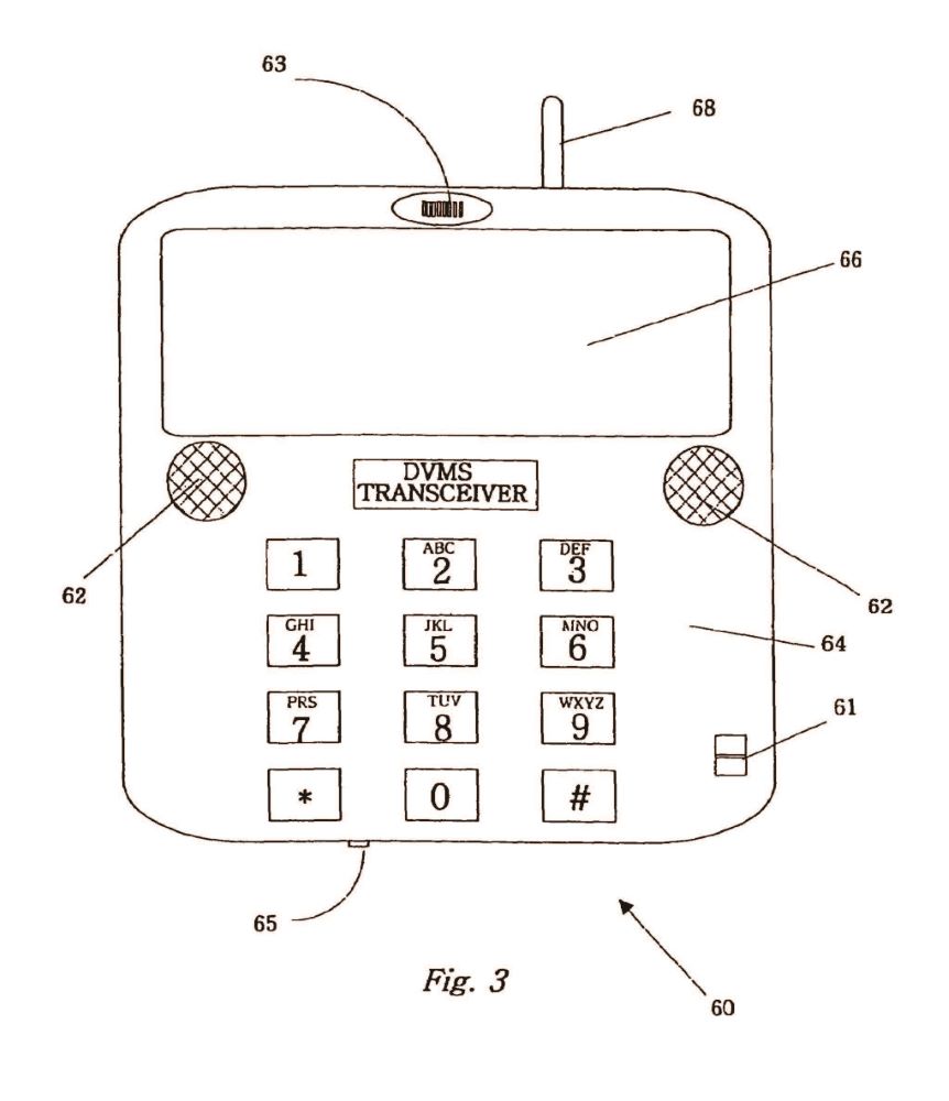
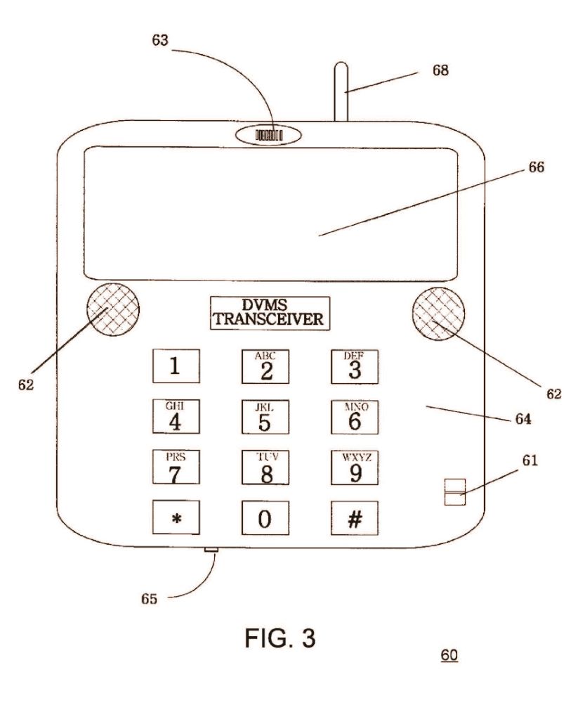
FIG. 3 is a planar view of the DVMS transceiver.
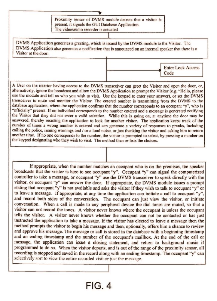
FIG. 4 is a block diagram overview of the method wherein the audio-video communication and answering system is employed as a door answering and messaging system.
FIG. 5 a block diagram extension of the method described in FIG. 4 wherein, additionally, there is an electronically actuated lock.
It is to be understood that the drawings are merely illustrative of the invention and are not meant to limit the claims. Various modifications and additions may be made to the apparatus by those skilled in the art, without the parting of the spirit and scope of this invention, which is therefore understood to be limited only by the scope of the appended claims. Further, the same reference numerals refer to the same parts throughout the various figures.
DETAILED DESCRIPTION OF THE ILLUSTRATED EMBODIMENT
The major components of the audio-video communication and answering system 100 are schematically shown in FIG. 1. The exterior of a premises is differentiated from the interior by a demarcation line 214, which represents a wall or other similar structure. The wall 214 has a door 114 and an electronically actuated lock 116. On the exterior is a DVMS module 10, which is in wireless communication with a wireless RF router 42 that is on the interior. It is anticipated that there could be multiple entrances to the premises and multiple DVMS modules. The RF router 42, as shown in FIG. 1, is separate from the computerized controller, which is a personal computer 80, however, the RF router 42 could easily be part of the personal computer 80. A DVMS device is a device that communicates via short-range RF waves (preferably FM) that have a direct view, in that the RF waves can pass through doors, walls and floors. These peripheral devices are used to receive and convey messages to other DVMS devices, as well as the personal computer 80. Also in communication with the RF router 42 is a DVMS transceiver 60. Two are shown, but obviously there could be less or more. A speaker 44 is in communication with the personal computer 80. The speaker 44 is not shown as wireless, but could be. One is shown, but obviously there could be more. A DVMS Database Application 82 is running on the PC 80. The DVMS Database Application, in concert with the operating system, controls the communication to the audio-video equipment, including the DVD-R/W 84, the CD-ROM R/W 92, and the hard drive 86. Depending on the owner's preference, there is no critical need for the DVD 84 nor for the write functionality of the CD-ROM 92, however, a larger hard drive would then be necessary. Typically, these components are housed in the PC, but for clarity they have been shown outside, connected to a switch 88 instead of a bus. Depending on the switch 88, additional audio-video storage devices can be used. No camera is shown, as it is not critical to the system, but obviously any number of cameras could also be employed on the interior. Also shown is a voice generator 90, and this is used to generate the prompts, which either exists as pre-recorded messages, or are generated by a voice synthesizer. The personal computer, as previously stated, is connected to the Internet. The connection can be by satellite, DSL, or cable modems. An expanded version of the Internet known as the Grid can also be accessed. The personal computer 80 can actuate the lock 116. The personal computer, as previously stated, is also connected to the public switching telephone network (PSTN), which in turn enables communication with any device that connects to it, including GPS navigational systems (i.e., ONSTAR®)) 74, Video phones 72, cell phones 76 and PC computers 78, which include the personal digital assistants, PC's, laptops, etc. This last category, in addition to using telephone lines, can also communicate over the Internet. While not explicitly shown, it is anticipated that in addition to voice generation, the application can utilize voice recognition and image recognition.
The DVMS module 10 is shown in FIG. 2. As is readily seen in the figure, the DVMS module is capable of being portable, much like a cell phone. However, there are some important distinctions, the most notable being that it communicates by short-range RF. The DVMS module 10 can be securely mounted and quickly connected to an electrical source. It is small, not much larger than a credit card, and is readily adaptable for use in external residential or commercial locations. The DVMS module is comprised of: a camera 22, at least one speaker 12, a proximity sensor 26, a microphone 20, a LCD display 16, a locking mechanism 28, a quick connect electrical receptacle 24, a RF FM receiver/transmitter 18, and a keypad 14. The DVMS module 10 can, optionally, have a small portable energy source, such as a battery. The DVMS module 10 can be mounted in a holster (not shown). The LCD display can be used to send and receive text. Alphanumeric code can be generated by the keypad. The camera 22 is activated by the proximity sensor 26, which in turn relays an image, or streaming video to the PC 80 where it is saved in the database with a timestamp. The locking mechanism 28 enables the DVMS module 10 to be installed securely wherever holstered, or to be moved to some other remote location, if desired. Preferably, the DVMS module 10 is connected to an electrical supply having a battery backup.
Referring to FIG. 3, the DVMS transceiver 60 is portable and has many of the same components as the DVMS module 10. Like the DVMS module 10, the DVMS transceiver 60 communicates by short-range RF. Unlike the DVMS module 10, the DVMS transceiver 60 does not have weather resistance because it is used in the interior. The DVMS transceiver 60 is comprised of: at least one speaker 62, a microphone 50, a LCD display 66, a quick connect electrical receptacle 65 for charging, a RF FM receiver/transmitter 68, and a keypad 64. The LCD display 66 can be used to send and receive text. Alphanumeric code can be generated by the keypad 66. In a preferred embodiment the DVMS transceiver has a mute switch 61, which cuts off the microphone 63, thus assuring the user that if he wishes he can just monitor a video without ever accidentally sending an audible signal.
Referring to FIG. 4, which is a block diagram of the method wherein the audio-video communication and answering system is employed as a door answering and messaging system. The block diagram takes the reader through a typical scenario when the invention is deployed at a residence.
Referring to FIG. 5, which is a block diagram extension of the method described in FIG. 4 wherein, additionally, there is an electronically actuated lock. In the given scenario, one of the occupants is attempting to gain access to the premises. The block diagram walks the reader through the DVMS database application method.
In the foregoing specification, the invention has been described with reference to specific embodiments thereof. It will, however, be evident that various modifications and changes may be made thereto, without departing from the broader spirit and scope of the invention. Accordingly, the specification and drawings are to be regarded in an illustrative, rather than a restrictive sense. It is the intention to cover these and any other changes or modifications to the disclosed embodiments, which are encompassed by the claims appended hereto.
SUMMARY OF THE ACHIEVEMENT OF THE OBJECTS OF THE INVENTION
From the foregoing, it is readily apparent that we have invented an improved, audio-video communication and answering system that can be deployed as a door answering system.
The system provides the options of allowing the visitor to converse with the occupant, leaving a message, or calling a remote peripheral device for communication with the occupant when he is either not present or unavailable. The visit is recorded and time stamped for sorting or viewing either in real time or at a later date. The system achieves these features, while still presenting a system that is intuitive and easy to use. The system further enables an electronically actuated lock to be accessed by entering an access code, either with the DVMS module or remotely. A unique feature of the system is that when electrical power is lost, the system can be configured to call the administrator, or his designated representative, alerting him of the problem. The audio-video communication and answering system has esoteric features not found in the prior art, such as the flexibility to change a greeting, or prompt to reflect holidays, and special occasions. The system can incorporate music or sounds not found with answering systems, or even play images in the case where the DVMS module has an LCD display. Finally, the system allows the occupants to achieve a higher level of security and anonymity, if so desired.
The invention enables the administrator or a declared occupant to at any time to turn on the camera(s) and view the image(s), access the recorded the video images, or post a video image from his remote peripheral device to the video recorder.
It is to be understood that the foregoing description and specific embodiments are merely illustrative of the best mode of the invention and the principles thereof, and that various modifications and additions may be made to the apparatus by those skilled in the art, without departing from the spirit and scope of this invention, which is therefore understood to be limited only by the scope of the appended claims.
CLAIMS
1. An audio-video communication and answering system, said system comprising:
(a) at least one wireless exterior module having a proximity sensor, a video camera, a microphone, a speaker, an RF transmitter, and an RF receiver;
(b) a computerized controller running a software application;
(c) a wireless router, wherein the wireless router enables communication between the exterior module and the computerized controller;
(d) a recording component that records video and audio communication that is transmitted to and from the exterior module; and
(e) a playing component that plays video and audio communication recorded by the recording component;
(f) wherein the software application includes a graphic user interface that enables a user to view images and streaming video from the camera, and that enables the coordination of multiple communication devices and user defined responses to prompts and events.
2. The audio-video communication and answering system as claimed in claim 1, wherein the exterior module has a display screen.
3. The audio-video communication and answering system as claimed in claim 1, wherein the system is further comprised of an electronic connection to a public switching telephone network.
4. The audio-video communication and answering system as claimed in claim 1, wherein the exterior module is further comprised of a keypad that is a touch screen or a keyboard.
5. The audio-video communication and answering system as claimed in claim 4, wherein the exterior module is portable, has a locking mechanism, and an electrical receptacle for quickly attaching to a source of electricity.
6. The audio-video communication and answering system as claimed in claim 5, wherein the portable exterior module has a portable energy source and is secured in a holster.
7. An audio-video communication and answering system according to claim 1, wherein the system is further comprised of an interior transceiver having a display screen, a microphone, a speaker, an RF transmitter, and an RF receiver.
8. An audio-video communication and answering system according to claim 7, wherein the computerized controller is a personal computer.
9. The audio-video communication and answering system according to claim 8, wherein the personal computer has a video camera.
10. The audio-video communication and answering system according to claim 8, wherein the personal computer controls at least one additional storage device selected from the group consisting of a CD-ROM R/W, a DVD R/W, a camera card, a tape drive, and a hard drive.
11. The audio-video communication and answering system according to claim 7, wherein the interior transceiver can be used to generate text messaging.
12. An audio-video communication and answering system according to claim 1, wherein the system is connected to a digital communication channel selected from the group consisting of DSL, satellite, cable, wireless, and a combination thereof, where the digital communication channel is in communication through the Internet, the Grid, satellite systems, and other information sharing systems.
13. The audio-video communication and answering system according to claim 1, wherein said system is further comprised of remote peripheral devices selected from the group consisting of cell phones, telephones, video-cell phones, computers, personal digital assistants, video-personal digital assistants, satellite telephones, transceivers, pagers, and other digital communication devices.
14. The audio-video communication and answering system according to claim 13, wherein the video camera can be remotely actuated and streaming video can be viewed.
15. An audio-video communication and answering system according to claim 13, wherein the system is further comprised of an electronically actuated lock, which can be unlocked by the computerized controller.
16. An audio-video communication and answering system according to claim 15, wherein the system is further comprised of a voice recognition module.
17. An audio-video communication and answering system according to claim 15, wherein the system is further comprised of an image recognition module.
18. An audio-video communication and answering system according to claim 15, wherein the system is further comprised of a voice-generation apparatus.
19. The audio-video communication and answering system according to claim 18, wherein the voice generation apparatus is a voice synthesizer.
20. An audio-video communication and answering system according to claim 18, wherein the system is further comprised of a battery backup.
21. An audio-video communication and answering system according to claim 20, wherein the system is further comprised of a component that detects a loss in electrical power, and that sends a message to at least one remote peripheral device that there has been a loss of electrical power.
22. The audio-video communication and answering system according to claim 21, wherein the software application has various levels of access to a database defined by privileges, wherein there is at least one declared occupant and an administrator, and wherein the at least one declared occupant is a named individual who has privileges to actuate the lock by entering an access code into the exterior module.
23. An audio-video communication and answering system according to claim 11, wherein a communication interface is further provided for communicating with an alarm at a remote location to signal that there has been a security breach of the lock.
24. The audio-video communication and answering system according to claim 22, wherein the software application contains multiple control settings, wherein said control settings include a telephone number that is to be called when there is a loss of power; a list of declared occupants; alias names of declared occupants; one or more telephone numbers and messages addresses for the declared occupant; emergency numbers that are to be automatically called, such as the police, the fire department, relatives, private security companies; passwords for access to the database; privilege levels of the declared occupants, access codes for actuating the lock; a maximum number of wrong access code entries, before access is denied; either a default or a customized prompt for greeting a visitor; a prompt for requesting information from a visitor; a request instructing a visitor as to their choices in leaving a message, or contacting the declared occupant; an action that is to be initiated by the system based on the input by the visitor; a selection of background music or a video that is to be played at a particular time and date; a level of security that the system is to operate under; a hierarchy of storage of audio and video data; a location and number of backup devices and replications of the database; a number and network designation of exterior modules and interior transceivers; and a log of self-checks to confirm that all the components of the system are operational.
25. An audio-video communication and answering system according to claim 24, further comprising a voice recognition system.
26. A method for audio-video greeting and communicating with visitors at a business or residence, wherein said method utilizes at least one exterior module having a proximity sensor, a video camera, a microphone, a speaker, an RF transmitter, an RF receiver; a computerized controller, wherein the computerized controller has components for playing and recording video and audio media; an RF switching device that enables communication between the exterior module and the computerized controller; and a software application; said method comprising:
(a) detecting the presence of a visitor via the proximity sensor of the exterior module, where the exterior module is mounted at or near an entrance, wherein upon detection the computerized controller is signaled that a visitor is present;
(b) actuating the components for playing and recording video and audio media, and saving a recording in a location in the database with a beginning time-stamp;
(c) broadcasting that a visitor is present;
(d) issuing a greeting to the visitor, and asking the visitor to state a reason for their visit;
(e) observing an image or video of the visitor displayed on the computerized controller;
(f) if appropriate, issuing a prompt stating that occupant "y" is not available and asking the visitor if they wish to talk to occupant "y" or to leave a message;
(g) if appropriate, initiating a call to occupant "y";
(h) if appropriate, asking the visitor to begin his message;
(i) attaching a message beginning with a timestamp and an occupant mailbox designation in the database;
(j) time stamping the end of message;
(k) if appropriate, issuing a closing statement;
(l) when the visitor has finished the message and is out of the range of the proximity sensor, stopping all recording and time stamping the end of the recording, wherein the occupant "y" can, remotely or locally, selectively sort and view the entire recorded visit or just the message.
27. A method for audio-video greeting and communicating with visitors of a business or residence according to claim 26, wherein said method further utilizes an electronically actuated lock, said method further comprising, upon a visitor entering an access code into the exterior module, checking the database to confirm that the access code is correct and actuating the lock if correct.
28. A method for audio-video greeting and communicating with visitors of a business or residence according to claim 27, said method further comprising, upon entrance of the visitor entering an access code into the exterior module that corresponds to the access code assigned to a declared occupant, notifying a specified occupant that the declared occupant has now entered the premises.
29. A method for audio-video greeting and communicating with visitors of a business or residence according to claim 27, wherein the specified occupant can remotely monitor or review the visitor entering the access code.
30. A method for audio-video greeting and communicating with visitors of a business or residence according to claim 27, wherein a maximum number of wrong entries of the access code automatically actuates a call to the specified occupant, and/or shuts down access to the premises.
CITATIONS
| Cited Patent | Filing date | Publication date | Applicant | Title |
|---|---|---|---|---|
| US5148468 | Oct 24, 1990 | Sep 15, 1992 | Arnold; Gregory J. | Door answering system |
| US5303300 | Jun 29, 1992 | Apr 12, 1994 | Eckstein; Donald | Security door phone device |
| US5406618 | Oct 5, 1992 | Apr 11, 1995 | Phonemate, Inc. | Voice activated, handsfree telephone answering device |
| US5657380 | Sep 27, 1995 | Aug 12, 1997 | Sensory Circuits, Inc. | Interactive door answering and messaging device with speech synthesis |
| US5896165 | Apr 9, 1997 | Apr 20, 1999 | Texas Instruments Incorporated | Method and system for a video answering machine |
| US5966432 | Apr 14, 1997 | Oct 12, 1999 | Nortel Networks Corporation | Remote answering of doorbell |
| US6041106 | Jan 15, 1997 | Mar 21, 2000 | Elite Entry Phone Corp. | Access control apparatus for use with buildings, gated properties and the like |
| US6049598 | Aug 28, 1997 | Apr 11, 2000 | Alcatel | Facility for tying a door intercommunication system with a video camera to an integrated services digital network |
| US6185294 | Feb 3, 1998 | Feb 6, 2001 | Chornenky O. Joseph | Method and apparatus for installing telephone intercom-voice messaging apparatus at doorbell for dwelling |
| US6233328 | Apr 1, 1996 | May 15, 2001 | Wolf Michael | Door intercom |
| US6324261 | Apr 28, 1998 | Nov 27, 2001 | Merte Donald A. | Door answering machine |
| US6438221 | Sep 8, 1999 | Aug 20, 2002 | Buczek Joseph E. | Electronote wall mounted messaging device |
| US6504470 | Jan 16, 2001 | Jan 7, 2003 | Nextgenid, Ltd. | Access control method and apparatus for members and guests |
| US6509924 | May 3, 2001 | Jan 21, 2003 | Sharp Kabushiki Kaisha | Video telephone with automatic answering function |
| US6762788 | May 9, 2002 | Jul 13, 2004 | Tranwo Technology Corp. | Wireless video/audio transmission device for bi-directional communications |
| US7015946 | Apr 12, 2002 | Mar 21, 2006 | Aiphone Co., Ltd. | Television door intercom apparatus |
| USD413541 | Jul 23, 1998 | Sep 7, 1999 | Door answering system |
NON-CITATIONS
| 1 | "3006 Doorphone Trunk Port", publicly accessed via the Internet on May 13, 2002, <http://www.algosolutions.com/product/3006.htm>. |
| 2 | "Doorphone", publicly accessed via the Internet on May 13, 2002, <http://www.smarthome.com/images/5079dgmbig.jpg>. |
| 3 | "New Invention Provides Security and Convenience", The Cape Fear Messenger, newspaper article published on Mar. 30, 1988. |
| 4 | "Nortel Venture wired phone system", publicly accessed via the Internet on May 13, 2002, <http://shop.store.yahoo.com/phonesystem/norvanwirsys.html>. |
| 5 | "Venture Specifications", publicly accessed via the Internet on May 13, 2002, <http://www.gd-wts.com/widts/Vendor%20Info/venture.htm>. |
REFERENCE BY
| Citing Patent | Filing date | Publication date | Applicant | Title |
|---|---|---|---|---|
| US7583191 | Nov 14, 2006 | Sep 1, 2009 | Zinser Duke W | Security system and method for use of same |
| US8041016 | Feb 22, 2005 | Oct 18, 2011 | Anders Trell Trust | Method and device for access communication/control |
| US8120459 | Dec 14, 2006 | Feb 21, 2012 | Samsung Electronics Co., Ltd | Access authentication system and method using smart communicator |
| US8164614 | Oct 30, 2007 | Apr 24, 2012 | Revolutionary Concepts, Inc. | Communication and monitoring system |
| WO2009076650A1 | Dec 12, 2008 | Jun 18, 2009 | Mogreet, Inc. | Methods and systems for transmitting video messages to mobile communication devices |
FRONT
| Publication number | US8139098 B2 |
| Publication type | Grant |
| Application number | 11/618,621 |
| Publication date | Mar 20, 2012 |
| Filing date | Dec 29, 2006 |
| Priority date | Oct 15, 2002 |
| Also published as | 6 More » |
| Inventors | |
| Original Assignee | |
| U.S. Classification | |
| International Classification | |
| Cooperative Classification | |
| European Classification | H04N 7/14A2
H04N 7/14A3
|
| References | Patent Citations (41)
Non-Patent Citations (11)
|
| External Links |
DRAWINGS (13)


ABSTRACT
A method for receiving a person at an entrance comprises the steps of detecting the presence of a person at the entrance with a proximity sensor located proximate the entrance, transmitting video of the person at the entrance recorded using a camera located proximate the entrance to a computerized controller running a software application, and providing a graphic user interface to a remote peripheral device by which a user of the remote peripheral device may view the video of the person at the entrance.
DESCRIPTION
I. CROSS REFERENCE TO RELATED APPLICATION
This application is a continuation-in-part patent application of, and claims the benefit under 35 U.S.C. §120 to, U.S. patent application Ser. No. 10/682,185, filed Oct. 9, 2003, published as U.S. Patent Appl. Publication No. 2005/0285934 A1 and now granted as U.S. Pat. No. 7,193,644, which patent application is a nonprovisional patent application of U.S. patent application Ser. No. 60/418,384, filed on Oct. 15, 2002, expired. Each of these patent applications, patent application publication, and patent is hereby incorporated herein by reference.
II. BACKGROUND OF THE INVENTION
There are numerous problems presently associated with receiving visitors at a home or office. When the resident of the home or occupant of the office (hereinafter generally referred to as either resident or occupant) is absent, there is often no message for the visitors, no means to leave an interactive message for the resident, and no means to ensure that unwanted access is not obtained. Moreover, answering the call of someone at a door of a dwelling can present certain security risks to an occupant therein. This situation can be especially inconvenient when, for example, a delivery or repair person arrives and the resident is not present. When the resident is present, on the other hand, there are also problems associated with receiving visitors. Some visitors may be unwelcome, for example, and it is often not evident that a visitor is a threat or an annoyance until after the door is open.
There are many types of systems for receiving a person by an occupant or resident and/or on the behalf of the occupant or resident. Such systems include those disclosed in each of: U.S. Pat. No. 5,148,468 titled “Door Answering System”, which issued Sep. 15, 1992 to Marrick et al; U.S. Pat. No. 5,303,300 titled “Security Door Phone Device,” which issued Apr. 12, 1994 to Eckstein; U.S. Pat. No. 5,406,618 titled “Voice Activated, Hands Free Telephone Answering Device,” which issued Apr. 11, 1995 to Knuth, et al.; and U.S. Pat. No. 5,657,380 titled “Interactive Door Answering and Messaging Device with Speech Synthesis,” which issued to Mozer on Aug. 12, 1997. Nevertheless, a need remains for further improvement in such a system.
III. SUMMARY OF THE INVENTION
The invention includes many aspects and features. Moreover, while many aspects and features of the invention relate to, and are described in, the context of a system for receiving a person at an entrance, such as, an entrance to a home or business, the invention is not limited to use only in such context and may be used and has applicability in other contexts as well.
In one aspect of the invention, an audio-video communication system comprises a wireless exterior module located proximate an entrance, a computerized controller running a software application and a remote peripheral device. The wireless exterior module includes a proximity sensor for detecting a person at the entrance, a video camera for recording an image of the person at the entrance, a microphone for recording sound of the person at the entrance, a speaker for playing audio to the person at the entrance, a transmitter for communicating sounds and images of the person at the entrance, and a receiver for receiving communications at the wireless exterior module. The computerized controller is disposed in wireless electronic communication with the wireless exterior module via the transmitter and the receiver of the wireless exterior module. The computerized controller is configured to control recording of communications with the wireless exterior module and playback of such recording, and the software application includes a graphic user interface that enables a user to view images from the video camera communicated from the wireless exterior module. The remote peripheral device is configured to electronically communicate with the computerized controller for viewing an image from the video camera communicated from the wireless exterior module.
In a feature of the first aspect, the audio-video communication system further comprises a second wireless exterior module located proximate an entrance, with the second wireless exterior module having a proximity sensor for detecting a person at the entrance, a video camera for recording an image of the person at the entrance, a microphone for recording sound of the person at the entrance, a speaker for playing audio to the person at the entrance, a transmitter for communicating sounds and images of the person at the entrance, and a receiver for receiving communications at the wireless exterior module. The computerized controller running the software application is further disposed in wireless electronic communication with the second wireless exterior module via the transmitter and the receiver of the second wireless exterior module.
In another feature of this aspect, the remote peripheral device is configured to remotely actuate the camera of the wireless exterior module. In an additional feature, the graphic user interface enables a user to view streaming video with the remote peripheral device. In yet another feature, the remote peripheral device comprises a cell phone. In still yet another feature, the remote peripheral device comprises a video phone. In further features, the remote peripheral device comprises a computer and a personal digital assistant.
In an additional feature, the entrance comprises an entrance of a business. In another additional feature, the entrance comprises an entrance of a residence. In a further feature, the wireless exterior module includes a display screen. In still a further feature, the wireless exterior module includes a keypad comprising a touch screen or a keyboard. In yet a further feature, the wireless exterior module is portable and includes a locking mechanism and an electrical receptacle for quickly attaching to a source of electricity.
In another feature, the wireless exterior module has a portable energy source and is secured in a holster. In yet another feature, the computerized controller comprises a personal computer. In still yet another feature, the computerized controller is disposed in electronic communication with a public switching telephone network (PSTN).
In a further feature, the computerized controller is disposed in electronic communication with the Internet. In an additional feature, the audio-video communication system further comprises an electronically actuated lock that is configured to be unlocked by the computerized controller. In another feature, the system further comprises a voice recognition system.
In still a further feature, a transceiver includes the transmitter for communicating sounds and images of the person at the entrance and the receiver for receiving communications at the wireless exterior module. In yet another feature, the computerized controller includes an image recognition module for identifying at least one of faces, eyes, and fingerprints.
In a second aspect of the invention, a method for two-way audio-video communications between a first person at an entrance and a second person comprises the steps of (a) detecting, with a proximity sensor located proximate an entrance, the presence of a first person at the entrance; and (b) providing real time audio-video communications between the first person at the entrance and a second person using a wireless handheld device. Step (b) is done by (i) transmitting, to the wireless handheld device of the second person, video of the first person at the entrance recorded using a camera located proximate the entrance, (ii) transmitting, to the wireless handheld device of the second person, audio of the first person at the entrance recorded using a microphone located proximate the entrance, and (iii) transmitting, to a speaker located proximate the entrance for playing to the first person at the entrance, audio of the second person recorded using the wireless handheld device.
In a feature of this aspect, the transmitting includes wireless communications between both the camera and microphone located proximate the entrance and a computerized controller running a software application including a graphic user interface by which the audio-video communications between the first person and the second person are established. In another feature, the method further comprises the step of playing a recorded greeting to the first person at the entrance upon the detection of the first person at the entrance with the proximity sensor. With regard to this feature, the method further comprises determining, by a user with a remote peripheral device, the recorded greeting that is played through a graphical user interface. With further regard to this feature, the recorded greeting is selected by the user from a plurality of recorded greetings. It accordance with this feature, the recorded greetings are seasonal greetings. It is preferred that the recorded greeting includes audio and video.
In an additional feature, the method further comprises the step of posting, by the user from a remote peripheral device, a video greeting for presentation to a first person at the entrance. In further features, the wireless handheld device comprises a cell phone, a video phone, and a personal digital assistant.
In yet another feature, the entrance comprises an entrance of a business. In still a further feature, the entrance comprises an entrance of a residence. In another feature, the method further comprises the step of saving a recording of the two-way audio-communications in a database for later playback. In yet another feature, the method further comprises transmitting, to a video display located proximate the entrance for presentation to the first person at the entrance, video of the second person recorded using the wireless handheld device.
In an additional feature, the transmitting includes communications over the Internet. In further features, the transmitting includes communications over a cellular network and over a satellite network. In yet another feature, the method further comprises remotely actuating the camera located proximate the entrance using the wireless handheld device. In still further features, the step of remotely actuating the camera includes zooming an image of the first person at the entrance and remotely moving the camera to change the view of the camera.
In a third aspect of the invention, a method for receiving a person at an entrance comprises the steps of (a) detecting, with a proximity sensor located proximate an entrance, the presence of a person at the entrance; (b) transmitting, to a computerized controller running a software application, video of the person at the entrance recorded using a camera located proximate the entrance; and (c) providing, with the application software running at the computerized controller, a graphic user interface to a remote peripheral device by which a user of the remote peripheral device may view the video of the person at the entrance.
In a feature of this aspect, the method further comprises the step of saving, in accordance with the application software running at the computerized controller, the video of the person at the entrance in a database in association with a timestamp. In other features, the video is viewed using the remote peripheral device in real-time, viewed using the remote peripheral device after the person at the entrance has left, and is streamed to the remote peripheral device.
In an additional feature, the method further comprises the step of transmitting, to the computerized controller running the software application, audio of the person at the entrance recorded using a microphone located proximate the entrance; wherein the graphic user interface provided to the remote peripheral device further enables a user of the remote peripheral device to hear the audio of the person at the entrance. In another feature, the method further comprises the step of playing a recorded greeting to the person at the entrance upon the detection of the person at the entrance with the proximity sensor.
In another feature, the method further comprises determining, by a user with the remote peripheral device, the recorded greeting that is played through a graphical user interface. With regard to this feature, the recorded greeting may be selected by the user from a plurality of recorded greetings, the recorded greetings may be seasonal greetings, and the recorded greeting may include audio and video.
In yet another feature, the method further comprises the step of posting, by the user from the remote peripheral device, a video greeting for presentation to a person at the entrance. In other features, the remote peripheral device comprises a cell phone, a video phone, a computer, and a personal digital assistant. In still other features, the entrance comprises an entrance of a business and an entrance of a residence.
In still another feature, the method further comprises remotely actuating the camera located proximate the entrance using the remote peripheral device. In further features, the step of remotely actuating the camera includes zooming an image of the person at the entrance and remotely moving the camera to change the view of the camera.
In addition to the aforementioned aspects and features of the present invention, it should be noted that the present invention further encompasses the various possible combinations of such aspects and features.
IV. BRIEF DESCRIPTION OF THE DRAWINGS
One or more preferred embodiments of the invention now will be described in detail with reference to the accompanying drawings.
FIG. 1 is a schematic diagram of a system in accordance with a preferred embodiment of the invention.
FIG. 2 is a planar view of the font of a DVMS module of the system of FIG. 1
FIG. 3 is a planar view of the front of a DVMS transceiver of the system of FIG. 1.
FIG. 4 is a block diagram overview of a method in accordance with a preferred embodiment of the invention.
FIG. 5 a block diagram extension of the method of FIG. 4.
FIG. 6 is a schematic diagram of a system in accordance with another preferred embodiment of the invention.
FIG. 7 is a perspective view of the front of a wireless network camera of the system of FIG. 6.
FIG. 8 is a side view of the wireless network camera of FIG. 7.
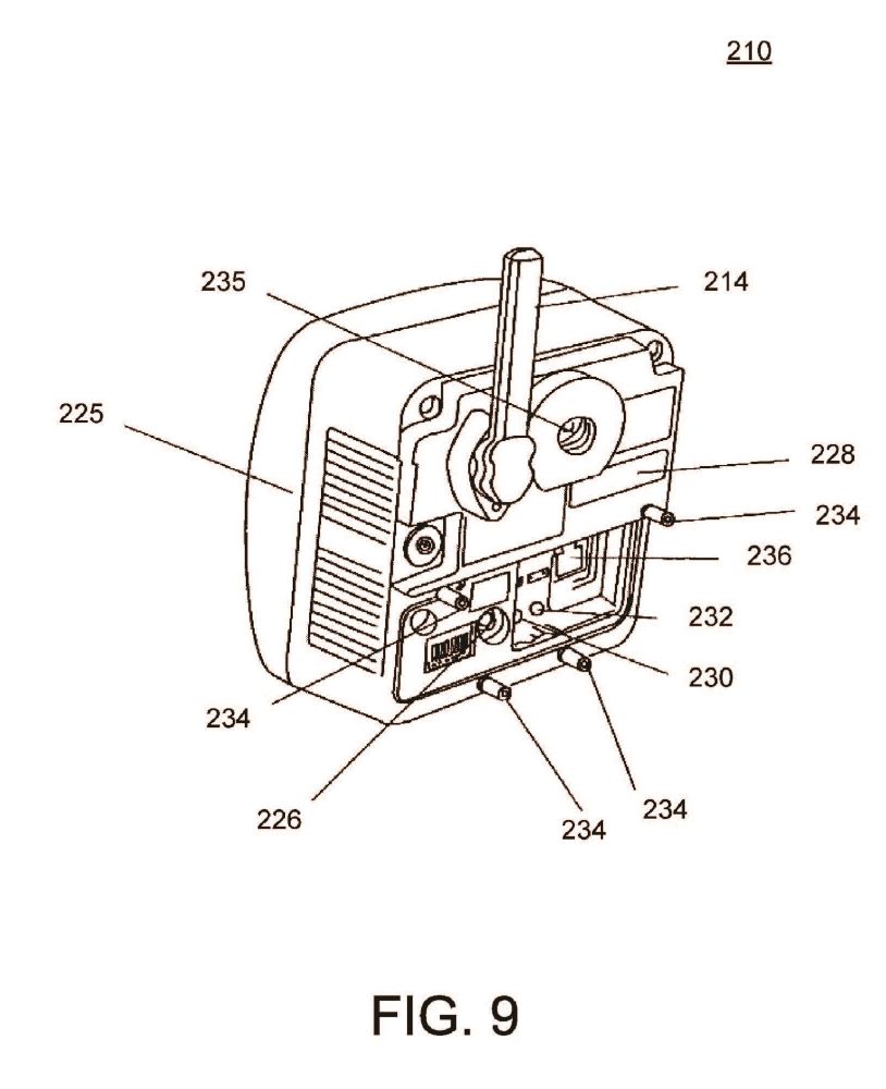
FIG. 9 is a perspective view of the rear of the wireless network camera of FIG. 7.
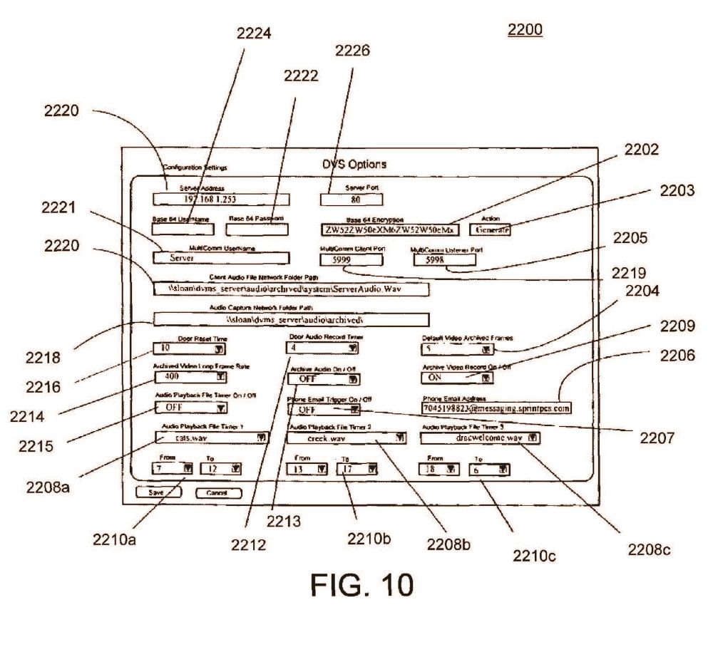
FIG. 10 is a representative screen view of a wireless command center of the system of FIG. 6, wherein various parameter settings for configuring, e.g., the audio, video, server, and cell phone options are illustrated.
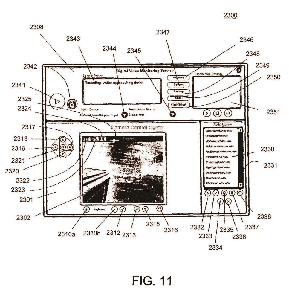
FIG. 11 is a screen view of the normal operating mode interface of the wireless command center of FIG. 10, wherein a user is able to dynamically control a wireless network camera, view video images generated by the wireless network camera, listen and send both pre-canned and live audio files, and review archived system events.
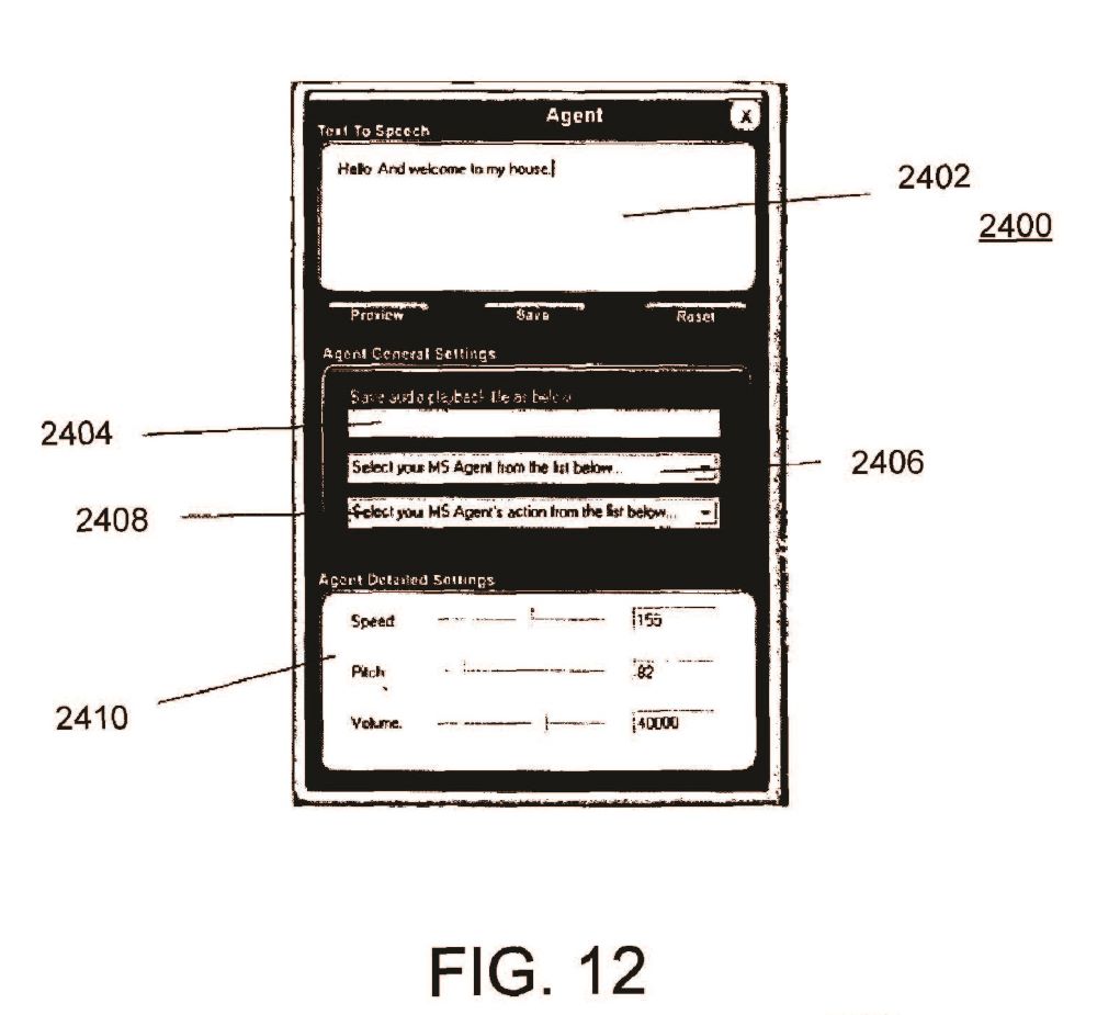
FIG. 12 is a dialog box screen view of the text-to-voice synthesizer module of the wireless command center of FIG. 10.
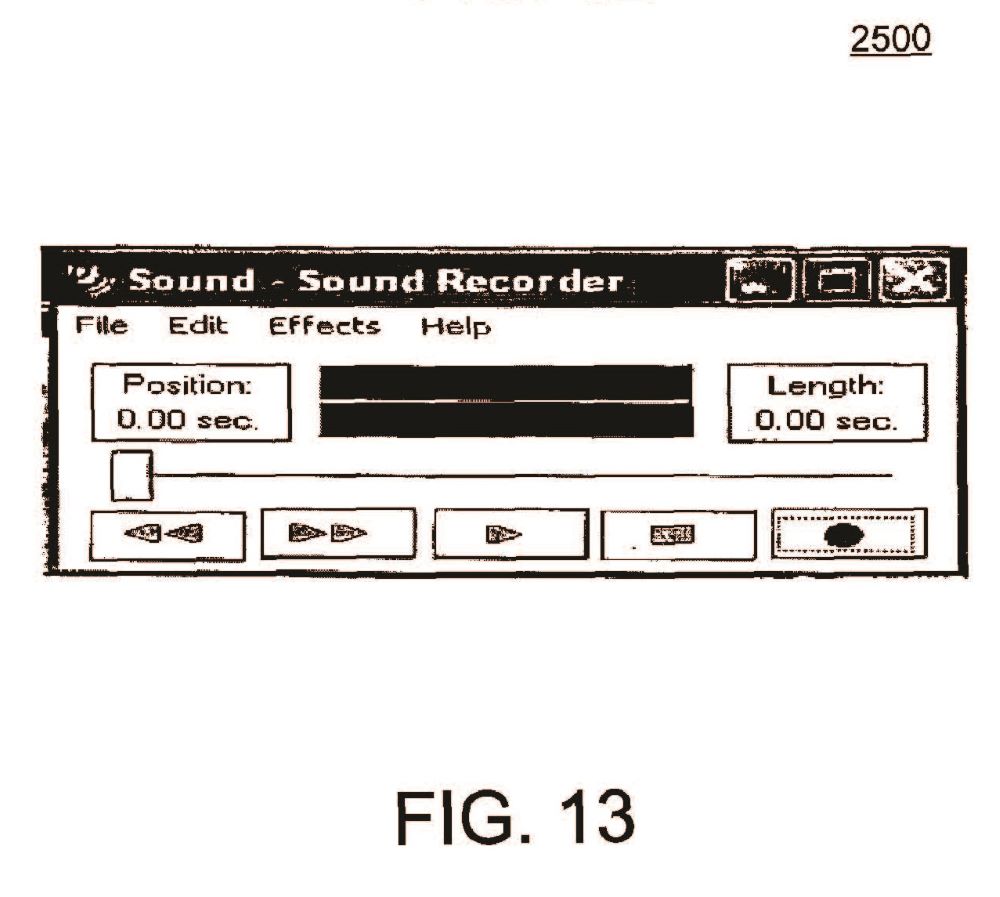
FIG. 13 is a dialog box screen view of the recorded voice synthesizer module of the wireless command center of FIG. 10.
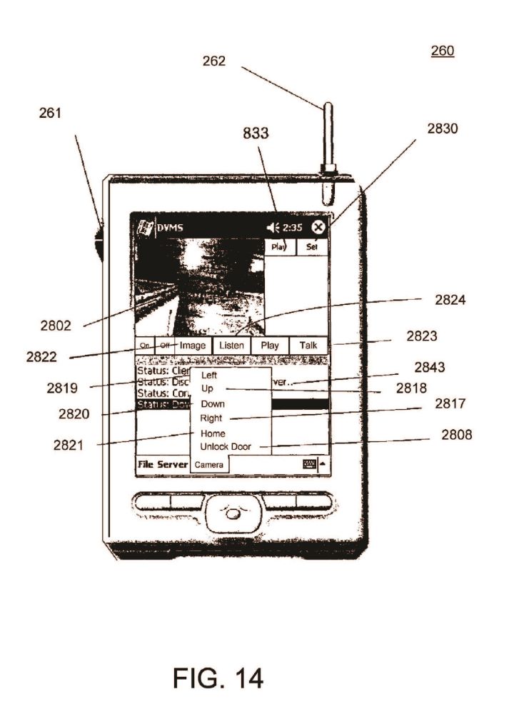
FIG. 14 is a planar view of the front of a wireless pocket PC that is connected to a wireless network, wherein a user of the wireless pocket PC is able to dynamically control the wireless network camera, view video images generated by the wireless network camera, listen and send both pre-canned and live audio files, and review archived system events in the system of FIG. 6.
V. DETAILED DESCRIPTION
As a preliminary matter, it will readily be understood by one having ordinary skill in the relevant art (“Ordinary Artisan”) that the present invention has broad utility and application. Furthermore, any embodiment discussed and identified as being “preferred” is considered to be part of a best mode contemplated for carrying out the present invention. Other embodiments also may be discussed for additional illustrative purposes in providing a full and enabling disclosure of the present invention. Moreover, many embodiments, such as adaptations, variations, modifications, and equivalent arrangements, will be implicitly disclosed by the embodiments described herein and fall within the scope of the present invention.
Accordingly, while the present invention is described herein in detail in relation to one or more embodiments, it is to be understood that this disclosure is illustrative and exemplary of the present invention, and is made merely for the purposes of providing a full and enabling disclosure of the present invention. The detailed disclosure herein of one or more embodiments is not intended, nor is to be construed, to limit the scope of patent protection afforded the present invention, which scope is to be defined by the claims and the equivalents thereof. It is not intended that the scope of patent protection afforded the present invention be defined by reading into any claim a limitation found herein that does not explicitly appear in the claim itself.
Thus, for example, any sequence(s) and/or temporal order of steps of various processes or methods that are described herein are illustrative and not restrictive. Accordingly, it should be understood that, although steps of various processes or methods may be shown and described as being in a sequence or temporal order, the steps of any such processes or methods are not limited to being carried out in any particular sequence or order, absent an indication otherwise. Indeed, the steps in such processes or methods generally may be carried out in various different sequences and orders while still falling within the scope of the present invention. Accordingly, it is intended that the scope of patent protection afforded the present invention is to be defined by the appended claims rather than the description set forth herein.
Additionally, it is important to note that each term used herein refers to that which the Ordinary Artisan would understand such term to mean based on the contextual use of such term herein. To the extent that the meaning of a term used herein—as understood by the Ordinary Artisan based on the contextual use of such term—differs in any way from any particular dictionary definition of such term, it is intended that the meaning of the term as understood by the Ordinary Artisan should prevail.
Furthermore, it is important to note that, as used herein, “a” and “an” each generally denotes “at least one,” but does not exclude a plurality unless the contextual use dictates otherwise. Thus, reference to “a picnic basket having an apple” describes “a picnic basket having at least one apple” as well as “a picnic basket having apples.” In contrast, reference to “a picnic basket having a single apple” describes “a picnic basket having only one apple.”
When used herein to join a list of items, “or” denotes “at least one of the items,” but does not exclude a plurality of items of the list. Thus, reference to “a picnic basket having cheese or crackers” describes “a picnic basket having cheese without crackers”, “a picnic basket having crackers without cheese”, and “a picnic basket having both cheese and crackers.” Finally, when used herein to join a list of items, “and” denotes “all of the items of the list.” Thus, reference to “a picnic basket having cheese and crackers” describes “a picnic basket having cheese, wherein the picnic basket further has crackers,” as well as describes “a picnic basket having crackers, wherein the picnic basket further has cheese.”
Referring now to the drawings, one or more preferred embodiments of the present invention are next described. The following description of one or more preferred embodiments is merely exemplary in nature and is in no way intended to limit the invention, its applications, or uses.
The System of FIG. 1
FIG. 1 is a schematic diagram of a system 100 in accordance with a preferred embodiment of the invention. For purposes of providing an enabling description, the system 100 is described in the context of a door answering system for receiving a person at a home or office and is capable of controlling access to the home or office. In FIG. 1, the exterior of the home or office is differentiated from the interior by demarcation line 115, which represents a wall or other similar structure. The wall 115 includes an entrance in the form of a door 114 and an electronically actuated lock 116 for selectively locking and unlocking the door 114.
A computerized controller in the form of a personal computer 80 is disposed in the interior and is configured to selectively actuate the lock 116. The personal computer 80 preferably includes a DVD-R/W 84, a CD-ROM R/W 92, and a hard drive 86. One or more of these components 84,92,86 of the personal computer 80 preferably are utilized for recording video and audio communications that are transmitted to and from the DVMS module 10 (described in further detail below) and for playing video and audio communications that are stored via the personal computer 80.
The personal computer 80 also may include a voice generator 90 for use in generating prompts, which either exists as pre-recorded messages or are generated by a voice synthesizer. Each of these components 84,92,86,90 of the personal computer 80 may be separately disposed from the personal computer and connected, for example, by a switch 88, or may form part of the personal computer 80 and be disposed in electronic communication with a bus of the personal computer 80 within the housing thereof.
A speaker 44 is disposed in electronic communication with the personal computer 80. The speaker 44 is not shown as being wireless, but could be. Moreover, one speaker 44 is shown, but additional speakers could be used in the system 100. Furthermore, speaker 44 in FIG. 1 is represented as being separate from the personal computer 80, however, the speaker 44 could alternatively form part of the personal computer 80.
The personal computer 80 preferably is disposed in electronic communication with the Internet. The connection with the Internet preferably is accomplished by a broadband connection such as a connection 81 provided by a satellite modem, a DSL model, or a cable modem, or any combination thereof.
The personal computer 80 also preferably is connected to a public switching telephone network (PSTN) 70, which enables communication by and with the personal computer 80 via standard telephone lines.
The personal computer 80 preferably has a battery backup as well as a means for detecting a loss in electrical power such that, when electrical power is lost the battery backup will provide sufficient operating time for the personal computer 80 to notify someone responsible for the maintenance of the system that there has been a loss of electricity. Notification of the loss of electricity can be important, since the loss of electrical power can be an indication of a burglary. Additionally, if there is no electricity, then appliances, such as refrigerators, air conditioners, and heaters, cannot function and significant damage can results if the electrical failure goes undetected for a substantial period of time.
The personal computer 80 runs a software application that includes a DVMS Database Application 82 and graphic user interfaces (GUIs). The personal computer 80, in accordance with the software application, controls communication in the system 100, coordinates multiple communication devices in the system 100, and is used to define responses to prompts and events in the system 100. The DVMS Database Application 82 and its uses are described in greater detail below.
The system 100 further includes a wireless router 42 located in the interior. The wireless router 42 in FIG. 1 is represented as being separate from the personal computer 80, however, the wireless router 42 could alternatively form part of the personal computer 80. The wireless router 42 is used to establish a wireless network and is disposed in electronic communication with the personal computer 80.
The system 100 also includes a DVMS module 10 located on the exterior of the home or office proximate the door 114. The DVMS module 10 is configured for use in the exterior of the home or office, which may include outdoor use in external residential or commercial locations. The DVMS module 10 is disposed in wireless communication with the wireless network, including the personal computer 80, via the wireless router 42.
With reference to FIG. 2, the DVMS module 10 preferably includes: a video camera 22; speakers 12; a proximity sensor 26; a microphone 20; an LCD display 16; a quick connect electrical receptacle 24; and a radiofrequency receiver/transmitter represented by antenna 18. The proximity sensor 26 activates the camera 22 upon detection of movement, which in turn relays an image or streaming video to the personal computer 80 where it is saved by the personal computer 80 in a database in association with a timestamp. Operation of the system is described in further detail below.
The DVMS module 10 optionally includes a small portable energy source, such as a battery that is rechargeable via the quick connect electrical receptacle 24, for portable use as well as for use in the event of a power failure.
The LCD display 16 screen preferably is a low energy screen reducing energy consumption. The LCD display 16 preferably comprises a touch screen and can be used to send and receive text similar to a keypad. Alternatively, or in addition thereto, the DVMS module 10 includes a keypad 14. In either case, the DVMS module 10 enables text messaging by a person at the exterior, which in turn enables a private non-audible conversation to be had and eliminates risks of eavesdropping by a passerby.
The DVMS module 10 also includes a locking mechanism 28 for receipt in a mounting holster (not shown). The locking mechanism 28 enables the DVMS module 10 to be installed securely wherever holstered, or to be moved to some other remote location, as desired. The DVMS module 10 thus is portable, much like a cell phone, and can be securely mounted and quickly connected to an electrical source.
It is anticipated that there could be multiple entrances to the home or office and, similarly, multiple DVMS modules similar to DVMS module 10 of FIG. 2 could be utilized, each disposed in wireless communication with the wireless network via the wireless router 42.
The system optional includes one or more DVMS transceivers 60. The DVMS transceivers 60 is configured for use in the interior of the home or office. As illustrated in FIG. 1, a DVMS transceivers 60 may be disposed in wireless communication with the wireless network, including the personal computer 80, and the DVMS module 10, via the wireless router 42. Additionally or alternatively, a DVMS transceivers 60 may be configured to wirelessly communicate directly with the DVMS module 10, thus bypassing communications through the wireless router 42.
With reference to FIG. 3, each DVMS transceiver 60 is portable and, like the DVMS module 10, the DVMS transceiver 60 communicates by short-range radiofrequency transmissions. The DVMS transceiver 60 includes: speakers 62; a microphone 63; an LCD display 66; a quick connect electrical receptacle 65; and a radiofrequency receiver/transmitter represented by antenna 68. The DVMS transceiver 60 optionally includes a small portable energy source, such as a battery that is rechargeable via the quick connect electrical receptacle 65, for portable use as well as for use in the event of a power failure. The DVMS transceiver 60 further includes a mute switch 61, which cuts-off the microphone 63, thus assuring a user of the DVMS transceiver 60 that a visitor can be monitored using the DVMS transceiver 60 without inadvertently sending an audible signal from the user.
The LCD display 66 screen preferably is a low energy screen reducing energy consumption. The LCD display 66 preferably comprises a touch screen and can be used is used to send and receive text similar to a keypad. Alternatively, or in addition thereto, the DVMS transceiver 60 includes a keypad 64. In either case, the DVMS module 60 enables text messaging by a user of the DVMS transceiver 60 with a person at the exterior using the DVMS module 10, which in turn enables a private non-audible conversation to be had and eliminates risks of eavesdropping by a passerby.
The system 100 further includes one or more remote peripheral devices. Such devices generally include video phones 72; in-car communication systems such as the well known ONSTAR system 74 currently found in GM cars; telephones 76; cell phones 77; personal computers 78; smartphones/personal digital assistants (PDAs) 79; and other similar communication devices. Each remote peripheral device is configured for electronic communication with the personal computer 80 via at least the PSTN connection 70 or the broadband connection 81.
As mentioned above, the personal computer 80 runs a software application that includes a DVMS Database Application 82 and graphic user interfaces (GUIs). The software application is configured and maintained by an administrator, who defines users thereof. The users in the system 100 are referred to as “occupants” reflecting their relation to the home or office.
Preferably, the occupants have various levels of access to the software application, depending on the privileges set by the administrator. The administrator may also set a level of security under which the system is to operate, particularly with respect to connections made using remote peripheral devices.
Other examples of configuration settings of the software application that are determined by the administrator include: aliases for a declared occupant such as, e.g., “Daddy” or “Momma”; passwords to access the software application; access codes to actuate the electronic lock controlled by the computerized controller; a number or other identifier that corresponds to an occupant's name; and at least one telephone number by which an occupant can be reached. The administrator also preferably defines a preferred hierarchy of storage of audio and video data, the location and number of backup devices, and whether replications of the database are to be kept.
Additionally, when setting up the software application, the administrator chooses, inter alia: a prompt for greeting a visitor; chooses an announcement that is to be given over a speaker within the interior when a visitor arrives; a prompt for requesting information from a visitor; a request instructing a visitor as to their choices in leaving a message or contacting a declared user; and the action that is to be performed by the computerized controller based on the input by the visitor.
The administrator also tailors the security/premise monitoring response by, inter alia: designating telephone numbers that the computerized controller calls when, for example, there is a loss of power; and designating telephone emergency numbers (e.g., telephone numbers for the police, the fire department, relatives, private security companies) that the computerized controller calls when an emergency is detected. The computerized controller also conducts self checks to confirm that all the components of the system are operational and keeps a log of the self checks, and the computerized controller preferably calls one or more designated numbers when a self check indicates a failure or otherwise improper operation.
The software application also can be configured to play background music or videos at different times of the year and/or different times of the day to reflect seasonal holidays, birthdays, and events. For instance, on Halloween the administrator may wish to have scary music and howls issuing from the DVMS module for receiving a person at that time. Furthermore, utilizing the computerized controller, the administrator can choose to use default prompts for interacting with a visitor or create customized prompts.
As hardware is added, such as the number of the DVMS modules and DVMS transceivers, the administrator can update both the network to include the additional devices and the computerized controller to accommodate the additional devices.
The software application also is configured to send voice, text, and video messages via email. The administrator can further set up redundant subsystems of the system 100.
The system 100, in use, enables secure and effective monitoring and interacting with a visitor at a residence or business, including, inter alia: the detection of the presence of a visitor at the exterior of the home or office via the proximity sensor 26, the interactive communication with the visitor, whether an occupant is present or absent from the home or office, the enablement of automated entry into the home or office by the visitor, and personalization of the process of receiving a visitor.
An exemplary method of use in the system 100 includes greeting and communicating with visitors of a business or residence. In accordance with the method, the presence of a visitor is detected via the proximity sensor 26 of the DVMS module 10, where the DVMS module 10 is mounted at or near an entrance to the business or residence. Upon the detection of the visitor by the proximity sensor 26, a message is communicated to the personal computer 80 from the DVMS module 10 indicating the detection of a visitor at the entrance. A recording is actuated by the personal computer 80, and the recording is stored in a computer-readable medium such as a database along with a beginning time-stamp. The arrival of a visitor is broadcast over a speaker within the home or office, such as speaker 44. An occupant can view the visitor on a display on the DVMS transceiver 60 or on a display of the personal computer 80, and the occupant can initiate a conversation at any time. The DVMS module 10 issues a greeting to the visitor and instructs the visitor to select a number from the keypad 14 of the DVMS module 10 in order to designate the occupant being visited. The entered number is communicated from the DVMS module 10 to the personal computer 80, where the software application confirms that the number corresponds to an occupant “y” who is “officially” present. An error message is generated if no individual corresponds to the number entered by the visitor. If no individual corresponds to the number entered by the visitor, then the visitor is prompted to select and press another number on the keypad 14 again designating the occupant being visited. The method then lists the choices again.
While this is going on, the door may be answered at any time, thereby resetting the software application to look for another visitor. The software application keeps track of the number of times a wrong number is entered and can generate a variety of responses to pranks, including calling the police, issuing warnings and/or a loud noise, or just thanking the visitor and asking him to return another time.
If appropriate, when the number designated by the visitor matches an occupant who is officially on the home or office, the speaker broadcasts that the visitor is here to see occupant “y”. Occupant “y” can signal the personal computer 80 to take a message, or occupant “y” may choose to use the DVMS transceiver 60 to speak directly with the visitor, or occupant “y” can answer the door.
If appropriate, the DVMS module 10 issues a prompt stating that occupant “y” is not available and asks the visitor if they wish to speak to occupant “y” or to leave a message.
If appropriate, at any time the software application can initiate a call to occupant “y” via a remote peripheral device for communication between occupant “y” and the visitor, and the software application can record both sides of the conversation between occupant “y” and the visitor. The occupant can view the visitor or initiate a conversation, as the occupant desires. A visitor never knows where the occupant is, unless the occupant tells the visitor of the occupant's location. A visitor also never knows if the occupant can be contacted, or if the occupant has just instructed the application to take a message. Using the method the conversation or messages can be relayed to the selected occupant without the visitor ever knowing where the location of the occupant. Only the occupant can disclose such location to the visitor as desired.
If the visitor elects to leave a message, then the method prompts the visitor to begin his message and then, optionally, offers him a chance to review and approve his message. The message or call is stored in computer readable medium, such as database, by the personal computer 80 in association with a beginning timestamp and an ending timestamp along with the occupant's mailbox number. At the end of the call or message, the software application can issue a closing statement and return to background music, if programmed to do so.
When the visitor departs, and is out of the range of the proximity sensor 26, all recording is stopped and saved in the database record, along with an ending timestamp. The occupant “y” can selectively sort to view the entire recorded visit, or just the message.
If the proximity sensor 26 indicates that there is another visitor, the method cycles back to the greeting step.
If the system has an electronically actuated lock, then the method also may include the steps of checking the number entered by the visitor to determine if it is a valid access code. The electronically actuated lock may be unlocked by entering an access code either at the DVMS module 10 or remotely therefrom. If the number is valid, then the lock is actuated, and if the number is not valid, then a prompt is made requested that the code be re-entered. Optionally, the prompt may further request a number be entered that corresponds to one of the occupants if assistance is needed and, if an occupant is selected, then calling the selected occupant. The method also may include tracking how many times the wrong code is entered; checking if the maximum allowed number of wrong entries have been made; and, when the maximum number of wrong entries is reached, either automatically calling a designated party and/or removing access privileges.
An occupant preferably has the option of remotely entering the access code, thereby actuating the electronically actuated lock, or instructing the GUI database application to go to a new high security level, wherein the lock cannot be accessed and notifying the visitor that the access code is not operational.
In the method, upon the entering of a valid access code assigned to a declared occupant, the software application optionally notifies the administrator or his designated representative that the declared occupant has now entered the home or office. The administrator would know who the individual should be. The administrator thus can confirm, by remotely viewing the recorded video, that the actual person who entered the access code is the declared occupant, and/or make a follow-up telephone call to the home or office. The system 100 also provides the options of allowing the visitor to converse with the occupant, leaving a message, or calling a remote peripheral device for communication with the occupant when he is either not present or is unavailable. The entrance is recorded and time stamped for sorting or viewing either in real time or at a later date.
The system 100 further enables the administrator or a declared occupant to, at any time, to turn on a camera and view images, access the recorded the video images, or post a video image from a remote peripheral device to computerized controller including associated components.
The system 100 preferably is inherently extensible in both form and function and is designed so that the system can be expanded to include multiple peripheral devices, both in direct and indirect communication with the computerized controller. Due to the use of the computerized controller and its interconnectivity, the disclosed system 100 can be configured to accommodate communications having a range of complexity.
As will be apparent from the foregoing, the system 100 provides an audio-video communication and answering system that provides real time communication between an exterior of a business or residence and an interior of the business or residence as well as a location remotely located to the business or residence.
As will be apparent from the foregoing, the system 100 provides an audio-video communication and answering system that provides real time communication between two or more rooms at a home or office and a remote location.
As will be apparent from the foregoing, the system 100 provides an audio-video communication and answering system that provides the ability to leave messages at a centralized location from a local or remote location.
In addition to the foregoing description of a method, FIG. 4 shows a block diagram illustrating an example of the use of a system of the invention as a door answering and messaging system at a residence. Furthermore, FIG. 5 shows a block diagram illustrating an example of the use of a system of the invention as a door answering and messaging system at a residence, wherein the system includes an electronically actuated lock. In the example, an occupant is attempting to gain access to the home or office.
As will now be apparent, systems in accordance with the invention achieve one or more of the foregoing benefits and features yet remain intuitive and easy to use.
In addition to the foregoing, it further is anticipated that, in certain deployments of the invention, voice recognition would be useful, particularly when the system enables access to a home or office. Voice recognition adds another layer of security, and can be used to facilitate those individuals who are unable to press a keypad. Similarly, image recognition of faces, eyes and fingerprints can also be included in the system for authentication, security, and access. The software application thus alternatively utilizes voice recognition and/or image recognition.
Furthermore, while no camera is shown located within the home or office, any number of cameras could be utilized on the interior.
It will also be appreciated that a business may be a tenant located within a building shared by other businesses. A DVMS module for the business thus would be utilized on the exterior of the business, i.e., at the “front door” of the business, which would be located within the interior of the common building.
In variations of systems of the invention, it should further be noted that one or more devices having the functionality of DVMS modules could be utilized in the interior for securing entrance to a room or group of rooms.
The System of FIG. 6
FIG. 6 is a schematic diagram of a system 2100 in accordance with another preferred embodiment of the invention. The system 2100 includes: a local area network 2200; a wireless digital camera 210; and a computerized controller in the form of a personal computer 240 (identified as the “Wireless Command Computer” in FIG. 6). The lines indicate communications between member devices and components of the system 2100 and such communications may be wired, wireless, or a combination of both wired and wireless. For purposes of providing an enabling description, the system 2100 is described in the context of a door answering system for receiving a person at a home or office and is capable of controlling access to the home or office. In FIG. 6, the exterior of the home or office is differentiated from the interior by a wall 2112 or other similar structure. The wall 2112 includes an entrance in the form of a door 2116 and an electronically actuated lock 2114 for selectively locking and unlocking the door 2116.
The personal computer 240 is disposed in the interior and is configured to selectively actuate the lock 2114. The personal computer 240 includes one or more components utilized for recording video and audio communications and for playing video and audio communications. The personal computer 240 also may include a voice generator for use in generating prompts, which either exists as pre-recorded messages or is generated by a voice synthesizer. Each of these components of the personal computer 240 may be separately disposed from the personal computer and connected, for example, by a switch, or may form part of the personal computer 240 and be disposed in electronic communication with a bus of the personal computer 240 within the housing thereof. A speaker 248 is disposed in electronic communication with the personal computer 240. Moreover, one speaker 248 is shown, but additional speakers could be used in the system 2100. Furthermore, speaker 248 in FIG. 6 is represented as being separate from the personal computer 240, however, the speaker 248 could alternatively form part of the personal computer 240.
The personal computer 240 preferably is disposed in electronic communication with the Internet. The connection with the Internet preferably is provided by a broadband connection through, for example, a wireless router 250. Such broadband connection may be accomplished by a satellite modem, a DSL model, or a cable modem, or any combination thereof. The personal computer 240 also preferably is connected to a public switching telephone network (PSTN) 70, which enables communication by and with the personal computer 240 via standard telephone lines.
The personal computer 240 preferably has a battery backup as well as a means for detecting a loss in electrical power such that, when electrical power is lost the battery backup will provide sufficient operating time for the personal computer 240 to notify someone responsible for the maintenance of the system that there has been a loss of electricity. Notification of the loss of electricity can be important, since the loss of electrical power can be an indication of a burglary. Additionally, if there is no electricity, then appliances, such as refrigerators, air conditioners, and heaters, cannot function and significant damage can results if the electrical failure goes undetected for a substantial period of time.
With regard to the wireless router 250, it is represented as being separate from the personal computer 240, however, the wireless router 42 could alternatively form part of the personal computer 240. The wireless router 42 is used, inter alia, to establish a wireless network and is disposed in electronic communication with the personal computer 240. The router 250 is WiFi compliant, and operates using a standardized protocol such as, for example, 802.11(b) and/or 802.11(g).
The wireless router 250 facilitates two-way communication over the local area network 2200 among the member devices and components of the wireless network 2200. Furthermore, the wireless router 250 preferably is disposed in electronic communication with the Internet and facilitates two-way communication between the member devices and components of the wireless network 2200 and remote devices communicating over the Internet. Such remote devices generally include video phones 275; in-car communication systems, such as the well known ONSTAR system 274 currently found in GM cars; telephones 276; cell phones 277; personal computers 278; smartphones/personal digital assistants (PDAs) 279; and other similar communication devices. Each remote device preferably is configured for electronic communication with one or more of the member devices and components of the wireless network 2200 via at least the PSTN connection 270 or a broadband Internet connection. Additionally, a remote device may be configured to communicate with one or more of the member devices and components of the wireless network 2200 via direct wireless communications with the wireless router 250 when such remote device is within communications range of the wireless router 250. Such direct wireless communications with the wireless router 250 is illustrated with the cell phone 277 in FIG. 6.
The wireless command computer includes a digital video system application (“DVS App”) 242 and a monitoring application 244. The DVS App 242 provides a set of customizable operating parameters for the wireless digital camera 210. The set of digital video operating parameters may include parameters selected from the group of: a default camera position; a number of frames per second; sensitivity and threshold of a motion sensor; length of a session; frequency of motion detection; and sensitivity and threshold of the motion detector. These parameters are conveyed to the camera operation application, discussed in further detail below. The monitoring application 244 includes a camera control screen that displays the camera webpage; and an operating screen that displays a set of operating parameters. The set of operating parameters may include parameters selected from the group of: a card file for cross-referencing MAC ID'S with cameras and pocket PCs on the wireless network; paths for logging and archiving files received from the camera; camera webpage addresses; email addresses for users; telephone numbers for cell phones; a designated greeting when a motion sensor is triggered; and security parameters. The monitoring application 244 further includes an audio library screen that displays the contents of a library of pre-recorded audio files. Typically, at least one pre-recorded audio file is a greeting audio file. In the context of the system 2100, the audio file can be sent over the local area network 2200, and can include, for instance, sounds, music, voice recordings, synthesized noises, and the like. The means of generating an audio file can be a microphone that feeds to an AID converter, which creates a digital audio file, such as a wav file or MP3 file, or a voice synthesized digital audio file. The monitoring application 244 generally includes a means of generating an audio file, and a command computer website that provides a command webpage with graphic controls for reviewing archived files. The monitoring application can further include a set of monitoring parameters that define the criteria for keeping or deleting a video file in memory, wherein the criteria includes available memory on system, age of file, and priority. The monitoring application also can further include an option to designate that the digital camera transmit video and audio data to more than one member device of the wireless network, and/or to split up audio and video data to two or more member devices. This feature is desirable if, for instance, it is preferred that either audio or video not be sent, or if a network member device—for instance a cell phone—is not configured to process both audio and video data. The monitoring application 244 also can include settings for notifying one or more designated individuals or a security service if an alarm is activated or if a predetermined condition is otherwise detected by a sensor. Such sensors may include, for example, smoke detectors, carbon monoxide detectors, laser beam detectors, broken window detectors, temperature detectors, radiation detectors, radon detectors, open window, door detectors, or a combination thereof. Moreover, such sensors may communicate via the local area network 2200.
The system 2100 includes a wireless digital camera 210 located on the exterior of the home or office proximate the door 2116. The wireless digital camera 210 includes a website application 246 and a camera operation application 247. The wireless digital camera 210 is shown in further detail in FIGS. 7-9. The wireless digital camera 210 preferably creates a series of images that are stored as a series of jpeg files which are displayed on a webpage of a website application 246 that is unique to a given camera 210. The camera 210 also includes a microphone 218, and the sound recorded by the microphone is digitized as an audio file, such as a .wav file or an MP3 file, that is transmitted along with the video as an audio file. This camera 210 preferably has a splash resistant body 225, a lens cover 238 over lens 216, and a wireless transceiver for audio 2-way audio communication. Furthermore, this camera 210 can pan, tilt, or move to a pre-set position. The camera 210 includes a motion sensor that triggers video recording with surveillance image quality, refreshing its image 30 frames per second, and includes a charge coupled device sensor to compensate for low light conditions. Communications via the wireless camera 210 also preferably are encrypted. The splash resistant body 225 allows the camera 210 to be used indoors or outdoors. The camera 210 also supports IPv6 (Internet Protocol Version 6). The audio feature of the camera 210 uses a Java applet that is installed during the installation. The camera 210 has a memory card 222 that is protected by a sealing door 224, a proximity detector or motion sensor 220, a microphone 218, a power input 226, an external microphone port 230, a LAN port 236, and a speaker port 232. The illustrated camera 210 has four mounting legs 234 and a mounting stand hole 235. The antenna 214 projects from the rear of the camera. A suitable wireless digital camera that has weather resistance is the camera currently sold in the United States by Panasonic under the part number BB-HCM371.
Every camera in the system 2100 preferably can be uniquely identified by a media access control (MAC) address that enables the personal computer 240, and each device in the system 2100 having a web browser, such as, e.g., a Windows Internet Explorer browser, or a Firefox browser, to be in wireless communication with camera 210 through the wireless router 250. While only one camera 210 is shown in FIG. 6, multiple cameras can be included in the system 2100, each with its own unique website accessible by multiple devices in the system 2100 having Internet browsers. In addition to displaying the video and audio on the camera's webpage, the website application 246 of the camera 210 displays graphic controls for actuating the camera 210, such as panning right and left, up and down, zoom in and zoom out, and adjustments for the amount of ambient light. These controls are illustrated in FIG. 11.
As previously stated, the camera 210 has a motion sensor 220 for detecting the presence of a person or a moving object with an adjustable level of sensitivity and a trigger threshold for initiating video recording, and, optionally issuing a verbal response, such as a greeting. The verbal response is an audio file, which can reside in the camera's memory as well as in the personal computer, in which case the verbal response can be transmitted, via the local area network 2200, to the camera 210. The camera 210 typically has a pre-set or default position, which can be static or dynamic. For instance, the camera 210 can be programmed to pan back and forth through a pre-set cycle or to zoom in and out, or any combination thereof. The motion sensor 220 has parameters for setting the sensitivity and a trigger threshold for initiating video recording. Upon initiation, the camera automatically starts recording video, which is displayed on the camera webpage in the form of video images, typically in serial form. The recording further can be transmitted to the personal computer 240 for saving for later viewing. In an alternative embodiment, the camera does not include a motion sensor 220 in the form of an additional piece of hardware but, instead, detects motion via a software application that analyzes the video images. In this alternative, the camera 210 records images on a routine basis and, when motion is detected, a video recording is initiated and a verbal response optionally is provided. Such software can be executed at the personal computer 210 or can be executed at the camera 210 and form part of the camera application 247.
The website application 246 of the digital camera 210 provides a webpage with graphic controls for operating the camera and a viewing area for viewing video images. When activate for recording the camera 210 provides digital video images that are displayed on the webpage. The camera 210 can be activated manually or self-activated by the motion sensor 220 that detects the presence of a person or a moving object. The motion sensor 220 has an adjustable level of sensitivity and a trigger threshold for initiating video recording. The camera 210 has a memory cache for saving a designated number or series of transmitted video images. Typically, when activated for video recording, the camera also activates audio recording, which provides audio files on the webpage generated by the digital camera's microphone 218. The camera 210 also includes means including the speaker 218 for playing received audio files.
Referring to FIG. 10, the screen 2200 for setting the parameters of the DVS application 242 is illustrated. Communications over the local area network 2200 between the camera 210 and command computer 240 are established using a MAC address of the camera 210 and/or an IP address 2224 for the camera. The default port 2226 for communications is 80. The camera 210 recognizes an encrypted username and password 2202. The DVS application 242 encrypts the username 2224 and the password 2222, using the generator 2203, resulting in the encrypted version 2202. The hierarchical structure of the member devices of the wireless network is defined in 2220, 2219 and 2205. The command computer 240 designated is named “Server”, as shown in the Username textbox 2221. The client port for uploading audio files 2219 is given as port 5999. An example of a client is a pocket PC 260 or cell phone 277 having a web browser. The listener port 2205 for down loading audio files is port 5998. The camera 210 has access to the audio files in a network-shared folder having a designated path 2220. When a greeting/verbal response is triggered by the motion sensor 220, the file is read from the shared folder 2220. Audio files received by the command computer 240 from the camera 210 are saved in the audio capture folder 2218. The received audio files can be accessed by the client, pocket PC 260, or cell phone 277, as well as the command computer 240. The door reset time 2216 is a parameter that designates the length of time in seconds that must pass after the motion sensor 220 no longer detects a visitor before a recording is stopped. The door audio record timer 2212 is the length of a visitor's message in seconds. The default video archived frames 2209 is the number of images or frames that are saved as an archived file. The archived video file 2216 can be played back at various speeds. The archived video loop frame rate 2216 is in frames per millisecond. Recall that the camera is capable of generating 30 frames, or 30,000 frames per millisecond. This feature 2216 allows the video to be slowed down. If the administrator wishes to cut off archiving audio files, the administrator can select this in box 2213. If the administrator wishes to cut off archiving video files, the administrator can select this in box 2209. The audio files can be turned off completely by using the audio playback parameter 2215. The DVS application 242 can be set to send a message to a cell phone or another computer. The phone email trigger 2207 sets this parameter, and the email address is entered into phone email address parameter 2207. The DVS enables different greetings/verbal responses to issue depending on pre-set criteria. The time of day is one criterion. As shown in FIG. 10, there are three audio files: “cats.wav” 2208 a, “creek.wavn” 2208 b and “dracwelcome.wav” 2208 c, each of which will be triggered depending on the time of day. Pairs of boxes 2210 a are set from 7 to 12, text boxes 2210 b are set from 13 to 17, and text boxes 2210 c are set from 18 to 6. At 13 hours, or 1 PM, the greeting switches from “cats.wav” 2208 a to “creek.wavfl 2208 b, and at 6 PM the greeting switches from “creek.wav” 2208 b to “dracwelcome.wav” 2208 c. As will be discussed below, additional options also exist for playing the audio files.
As shown in FIG. 11, the camera's webpage is incorporated as a screen in the monitoring application 244 of the wireless command computer 240. In the screenshot of the monitoring application 2300 of FIG. 11, the lower main screen 2301 displays the camera webpage. The camera webpage is comprised of the streaming video images 2301, an icon 2322 for taking a snapshot, an icon 2323 enabling the user to talk via the camera using the command computer's microphone, an icon 2324 enabling the user to hear sound picked up by the camera's microphone 218, and icon 2325 enabling the user to zoom in and out. Additionally the webpage has graphic controls for remotely positioning the camera, adjusting brightness and automatic panning. The cross-shaped icon on the side has left arrow 2319 for turning the lens left, a right arrow 2317 for turning the lens right, an up arrow 2318 for turning the lens up, a down arrow 2320 for turning the lens down, and a center button 2321, which returns the camera to its default position. On the bottom of the webpage is an icon 2310 a for increasing the brightness when the light is low, and icon 2310 b for decreasing the brightness when the light is high. Icon 2312 sets the brightness to the default position, and icon 2316 is a reset button that returns all parameters to the factory settings. The camera automatically pans back and forth when button 2313 is clicked, and pans up and down when button 2315 is clicked. Panning is stopped by re-clicking the pan icons. The double curved arrow icon 2316 refreshes the camera controls. The audio library screen 2330 contains a list of all the currently recorded audio files. A scroll bar 2331 enables the user to quickly move down the list. To play a selection, a file is selected with the cursor, and then arrow icon 2332 is clicked. The check icon 2333 designates a file as a greeting/verbal response file. The square icon 2334 is the stop button, the plus icon 2335 initiates a module for adding a new audio file, the X icon 2336 deletes a selected audio file, the double arrow icon 2337 causes all checked audio files to be played in random order, and the icon 2338 is a reset button. The top screen 2308 contains a number of options, including starting and running the DVMS service. Large button 2341 turns the program off when clicked, and on when clicked again. Clicking on the lock icon 2342 actuates the door lock. Screen 2343 contains information about what is occurring at the camera, and other system performance information. Drop down icon 2344 opens a dialog box mapping all the sounds and multimedia properties. Drop list icon 2345 displays a list of input devices, such as the microphone on the command computer 240, when talking directly to the camera 210, which needs to be selected to conduct real time conversations. The connected devices screen 2351 displays a list of the wireless network deices, and whether they are currently available. The archives button 2346 activates a screen that lists all the archived video and audio files, and a timestamp for when they were created. The options button 2347 activates the DVS screen 2200 for configuring the application.
The camera has a software package that is run when initializing a new or an addition camera, where communication is established using the MAC address and the subsequent assignment of an IP address. Clicking the camera button 2348 starts that software. The about button 2349 has general information about the version of the DVMS system and contact information. The status button 2350 clears screen 2351.
When recording an audio file, the user can use a synthesizer module or voice recording module. The synthesizer module is a dialog box 2400 shown in FIG. 12, and the voice recording module is a dialog box 2500 shown in FIG. 13. The synthesizer module and the voice recording modules are Microsoft open source modules. In the voice synthesizer module, text is entered into screen 402 and then saved in path 404. An animated character/agent pops up on the command computer when the audio file is played, and characteristics of the agent are selected using screens 2406, 2408, 2410. For instance, a wizard can be selected as the MS Agent, and the wizard flies quickly, and speaks loudly with a low pitch. In FIG. 13, the user can record his or another's voice, or some sound, music, or other audible sound.
The local area network 2200 optionally includes one or more portable devices such as the pocket PC 260 represented in FIG. 6 and shown in detail in FIG. 14. The pocket PC 260 is configured with a client DVMS application. The pocket PC 260 is wireless, having antenna 262 that communicates with the personal computer 240 and the wireless digital camera 210 via wireless modem 250. Similar to the personal computer 240, the pocket PC 260 includes a display screen 2802 for viewing streaming video from the digital camera 210, an “Image” icon 2822 for saving a snapshot, a listen icon 2824 which plays audio from the camera, and a talk icon 2823 for transmitting audio to the camera. The audio volume is adjusted using thumb wheel 261. The pocket PC 260 further includes controls for pointing the camera in the desired direction including: menu selection 2819 for left, menu selection 2818 for up, menu selection 2817 for right, menu selection 2820 for down, and menu selection 2821 to return to the camera 210 the default position. The door lock is unlocked for access using menu selection 2808, which transmits an access code in the form of text to the locking mechanism 2114. The lower screen 2843 displays the status of member devices in the local area network 2200. The library of audio files is accessible through the set button 2830, and the play button 2833 selects the audio file to be played.
While not explicitly shown, it is anticipated that the system 2100 may include voice recognition and image recognition for additional security in authentication and access.
The system provides the options of allowing the visitor to converse with the occupant, leave a message, or call a remote peripheral device for communication with the occupant when he is either not present or unavailable. The visit is recorded and time stamped for sorting or viewing either in real time or at a later date. The system achieves these features, while still presenting a system that is intuitive and easy to use. The digital video monitoring system is extensible, scalable, and flexible in that the number of members of the wireless network can be readily expanded, the system provides and audio and video record of events, and a number of the components are currently off-the-shelf computerized devices that can be configured for the system. Finally, the system allows the users to achieve a high level of security and anonymity.
As will be apparent from the foregoing, the system 2100 enables wireless audio-video communication by all the member devices with each digital camera and the command computer; the system 2100 enables the option of having a visitor converse with an occupant, leave a message, or contact a remote device for communication with a member of the network that is offsite; the system 2100 enables a wireless digital camera to generate and audio and video recording of a visitor upon the sensing that a visitor is proximate the door, with the recording being viewed in real time, or at a later time, either locally or remotely; the system 2100 is highly extensible and can be easily adapted to control many cameras, the images of which can be simultaneously viewed by multiple individuals by merely browsing the individual camera's website that is unique to each camera. The system 2100 also is highly scalable due to the incorporation of a wireless network in the local area network 2200; the system 2100 enables an alarm and or automated calls to designated institutions and individuals when there is a security breach detected; the system 2100 allows users having the proper privileges to remotely permit entrance to a building; the system 2100 can be customized to reflect holidays, special occasions, and various levels of security.
Based on the foregoing description, it will be readily understood by those persons skilled in the art that the invention is susceptible of broad utility and application. Many embodiments and adaptations of the invention other than those specifically described herein, as well as many variations, modifications, and equivalent arrangements, will be apparent from or reasonably suggested by the present invention and the foregoing descriptions thereof, without departing from the substance or scope of the present invention. Accordingly, while the invention has been described herein in detail in relation to one or more preferred embodiments, it is to be understood that this disclosure is only illustrative and exemplary of the invention and is made merely for the purpose of providing a full and enabling disclosure of the invention. The foregoing disclosure is not intended to be construed to limit the present invention or otherwise exclude any such other embodiments, adaptations, variations, modifications or equivalent arrangements, the invention being limited only by the claims appended hereto and the equivalents thereof.
CLAIMS
1. A method for receiving a person at an entrance, comprising the steps of:
(a) detecting the presence of a person at the entrance;
(b) transmitting, to a computerized controller running a software application, video of the person at the entrance recorded using a camera located proximate the entrance; and
(c) providing, with the application software running at the computerized controller, a graphic user interface to a remote peripheral device by which a user of the remote peripheral device may view the video of the person at the entrance.
2. The method of claim 1, further comprising the step of saving, in accordance with the application software running at the computerized controller, the video of the person at the entrance in a database in association with a timestamp.
3. The method of claim 1, wherein the video is viewed using the remote peripheral device in real-time.
4. The method of claim 1, wherein the video is viewed using the remote peripheral device after the person at the entrance has left.
5. The method of claim 1, wherein the video is streamed to the remote peripheral device.
6. The method of claim 1, further comprising the step of transmitting, to the computerized controller running the software application, audio of the person at the entrance recorded using a microphone located proximate the entrance; wherein the graphic user interface provided to the remote peripheral device further enables a user of the remote peripheral device to hear the audio of the person at the entrance.
7. The method of claim 1, further comprising the step of playing a recorded greeting to the person at the entrance upon the detection of the person at the entrance.
8. The method of claim 7, further comprising determining, by a user with the remote peripheral device, the recorded greeting that is played through a graphical user interface.
9. The method of claim 8, wherein the recorded greeting is selected by the user from a plurality of recorded greetings.
10. The method of claim 8, wherein the recorded greetings are seasonal greetings.
11. The method of claim 8, wherein the recorded greeting includes audio and video.
12. The method of claim 1, further comprising the step of posting, by the user from the remote peripheral device, a video greeting for presentation to a person at the entrance.
13. The method of claim 1, wherein said remote peripheral device comprises a cell phone.
14. The method of claim 1, wherein said remote peripheral device comprises a video phone.
15. The method of claim 1, wherein said remote peripheral device comprises a computer.
16. The method of claim 1, wherein said remote peripheral device comprises a personal digital assistant.
17. The method of claim 1, wherein the entrance comprises an entrance of a residence or a business.
18. The method of claim 1, further comprising remotely actuating the camera located proximate the entrance using the remote peripheral device.
19. The method of claim 18, wherein said step of remotely actuating the camera includes zooming an image of the person at the entrance.
20. The method of claim 18, wherein said step of remotely actuating the camera includes remotely moving the camera to change the view of the camera.
21. The method of claim 1, wherein the presence of the person at the entrance is accomplished with a proximity sensor located proximate an entrance.
CITATIONS
| US4804945 | Oct 29, 1987 | Feb 14, 1989 | Millet; Terrance | Door alarm with infrared and capacitive sensors |
| US4931789 | May 12, 1988 | Jun 5, 1990 | Universal Photonix, Inc. | Apparatus and method for a universal electronic locking system |
| US5031228 | Sep 14, 1988 | Jul 9, 1991 | A. C. Nielsen Company | Image recognition system and method |
| US5148468 | Oct 24, 1990 | Sep 15, 1992 | Arnold; Gregory J. | Door answering system |
| US5303300 | Jun 29, 1992 | Apr 12, 1994 | Eckstein; Donald | Security door phone device |
| US5406618 | Oct 5, 1992 | Apr 11, 1995 | Phonemate, Inc. | Voice activated, handsfree telephone answering device |
| US5428388 | Jun 15, 1992 | Jun 27, 1995 | Richard von Bauer | Video doorbell system |
| US5657380 | Sep 27, 1995 | Aug 12, 1997 | Sensory Circuits, Inc. | Interactive door answering and messaging device with speech synthesis |
| US5896165 | Apr 9, 1997 | Apr 20, 1999 | Texas Instruments Incorporated | Method and system for a video answering machine |
| US5966432 | Apr 14, 1997 | Oct 12, 1999 | Nortel Networks Corporation | Remote answering of doorbell |
| US6041106 | Jan 15, 1997 | Mar 21, 2000 | Elite Entry Phone Corp. | Access control apparatus for use with buildings, gated properties and the like |
| US6049598 | Aug 28, 1997 | Apr 11, 2000 | Alcatel | Facility for tying a door intercommunication system with a video camera to an integrated services digital network |
| US6094213 | Apr 13, 1998 | Jul 25, 2000 | Samsung Electronics Co., Ltd. | Computer conference system with video phone connecting function |
| US6185294 | Feb 3, 1998 | Feb 6, 2001 | Chornenky O. Joseph | Method and apparatus for installing telephone intercom-voice messaging apparatus at doorbell for dwelling |
| US6233328 | Apr 1, 1996 | May 15, 2001 | Wolf Michael | Door intercom |
| US6317489 | Dec 12, 1997 | Nov 13, 2001 | Elite Access Systems, Inc. | Entry phone apparatus and method with improved alphabetical access |
| US6324261 | Apr 28, 1998 | Nov 27, 2001 | Merte Donald A. | Door answering machine |
| US6356192 | Aug 27, 1999 | Mar 12, 2002 | Royal Thoughts L.L.C. | Bi-directional wireless detection system |
| US6429893 | Jun 4, 1998 | Aug 6, 2002 | Xin Alfred X. | Security system |
| US6438221 | Sep 8, 1999 | Aug 20, 2002 | Buczek Joseph E. | Electronote wall mounted messaging device |
| US6466261 | Mar 20, 1998 | Oct 15, 2002 | Niles Parts Co, Ltd. | Door camera unit having a video memory |
| US6504470 | Jan 16, 2001 | Jan 7, 2003 | Nextgenid, Ltd. | Access control method and apparatus for members and guests |
| US6509924 | May 3, 2001 | Jan 21, 2003 | Sharp Kabushiki Kaisha | Video telephone with automatic answering function |
| US6759956 | Sep 19, 2001 | Jul 6, 2004 | Royal Thoughts, L.L.C. | Bi-directional wireless detection system |
| US6762788 | May 9, 2002 | Jul 13, 2004 | Tranwo Technology Corp. | Wireless video/audio transmission device for bi-directional communications |
| US6778084 | Jan 9, 2002 | Aug 17, 2004 | Chang Industry, Inc. | Interactive wireless surveillance and security system and associated method |
| US7015943 | Jul 11, 2003 | Mar 21, 2006 | Le, Thi Co | Premises entry security system |
| US7015946 | Apr 12, 2002 | Mar 21, 2006 | Aiphone Co., Ltd. | Television door intercom apparatus |
| US7046268 | Dec 19, 2002 | May 16, 2006 | Kyocera Corporation | Portable videophone unit |
| US7088233 | Jun 7, 2002 | Aug 8, 2006 | Royal Thoughts, Llc | Personal medical device communication system and method |
| US7136458 | Dec 23, 1999 | Nov 14, 2006 | Bellsouth Intellectual Property Corporation | Voice recognition for filtering and announcing message |
| US7162281 | Feb 20, 2003 | Jan 9, 2007 | Kim Dong Joo | Mobile phone holder |
| US7353042 | Aug 22, 2001 | Apr 1, 2008 | Unirec Co., Ltd. | Wireless call system |
| US7583191 | Nov 14, 2006 | Sep 1, 2009 | Zinser Duke W | Security system and method for use of same |
| US7839985 | Apr 13, 2005 | Nov 23, 2010 | Sk Telecom Co., Ltd. | System and method for visitor reception service in absence |
| US20020050932 | Oct 30, 2001 | May 2, 2002 | Ocean Systems Engineering Corporation | Environment and hazard condition monitoring system |
| US20070103541 | Dec 29, 2006 | May 10, 2007 | Revolutionary Concepts, Inc. | Two-way audio-video communication method for receiving person at entrance |
| US20070103548 | Dec 29, 2006 | May 10, 2007 | Revolutionary Concepts, Inc. | Audio-video communication system for receiving person at entrance |
| US20080117299 | Oct 30, 2007 | May 22, 2008 | Revolutionary Concepts, Inc. | Communication and monitoring system |
| US20080136908 | Oct 30, 2007 | Jun 12, 2008 | Revolutionary Concepts, Inc. | Detection and viewing system |
| USD413541 | Jul 23, 1998 | Sep 7, 1999 | Door answering system |
NON-CITATIONS
| 1 | "3006 Doorphone Trunk Port", publicly accessed via the Internet on May 13, 2002, . |
| 2 | "Doorphone", publicly accessed via the Internet on May 13, 2002, . |
| 3 | "New Invention Provides Security and Convenience", The Cape Fear Messenger, newspaper article published on Mar. 30, 1988. |
| 4 | "Nortel Venture wired phone system", publicly accessed via the Internet on May 13, 2002, . |
| 5 | "Venture Specifications", publicly accessed via the Internet on May 13, 2002, . |
| 6 | "Wireless-G Internet Video Camera-Model No. WVC54G-Send live video and audio to a web browser anywhere in the world!", LINKSYS A Division of Cisco Systems, Inc. Product Data Sheet, Copyright 2004 Cisco Systems, Inc. |
| 7 | "3006 Doorphone Trunk Port", publicly accessed via the Internet on May 13, 2002, <http://www.algosolutions.com/product13006.htm>. |
| 8 | "Doorphone", publicly accessed via the Internet on May 13, 2002, <http://www.smarthome.com/images/5079dgmbig.jpg>. |
| 9 | "Nortel Venture wired phone system", publicly accessed via the Internet on May 13, 2002, <http://shop.store.yahoo.com/phonesystem/norvanwirsys.html>. |
| 10 | "Venture Specifications", publicly accessed via the Internet on May 13, 2002, <http://www.gd-wts.com/widts/Vendor%20Info/venture.htm>. |
| 11 | "Wireless-G Internet Video Camera—Model No. WVC54G—Send live video and audio to a web browser anywhere in the world!", LINKSYS A Division of Cisco Systems, Inc. Product Data Sheet, Copyright 2004 Cisco Systems, Inc. |
REFERENCE BY
FRONT
| Publication number | US8144183 B2 |
| Publication type | Grant |
| Application number | 11/618,618 |
| Publication date | Mar 27, 2012 |
| Filing date | Dec 29, 2006 |
| Priority date | Oct 15, 2002 |
| Also published as | 6 More » |
| Inventors | |
| Original Assignee | |
| U.S. Classification | |
| International Classification | |
| Cooperative Classification | |
| European Classification | H04N7/14A3
H04N7/14A2
|
| References | Patent Citations (41)
Non-Patent Citations (11)
|
| External Links |
DRAWINGS (14)
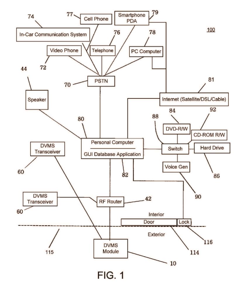
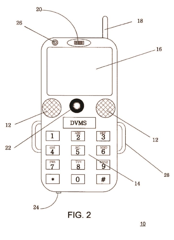
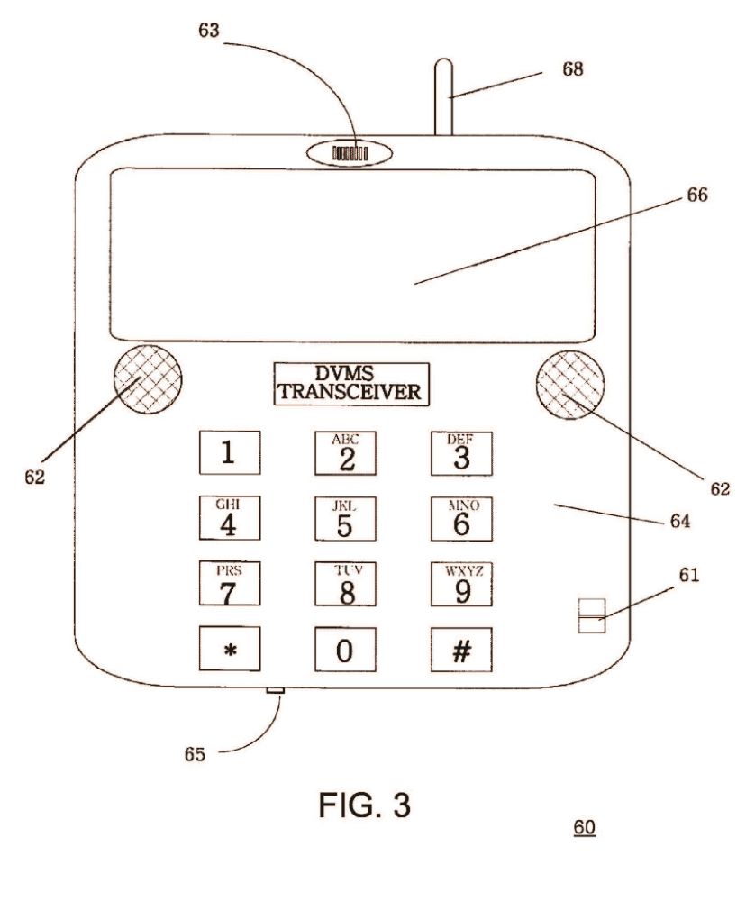


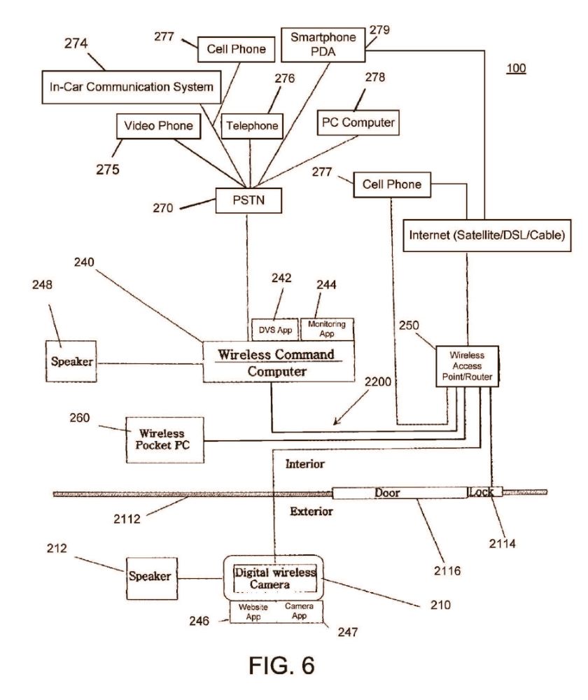
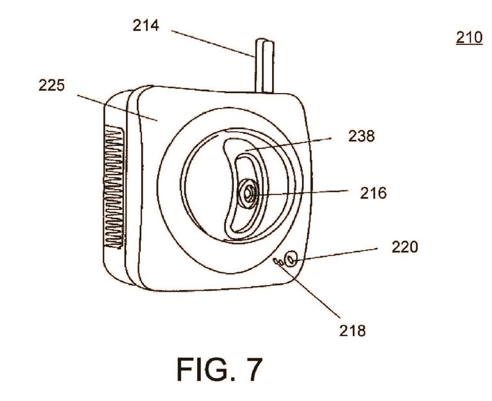
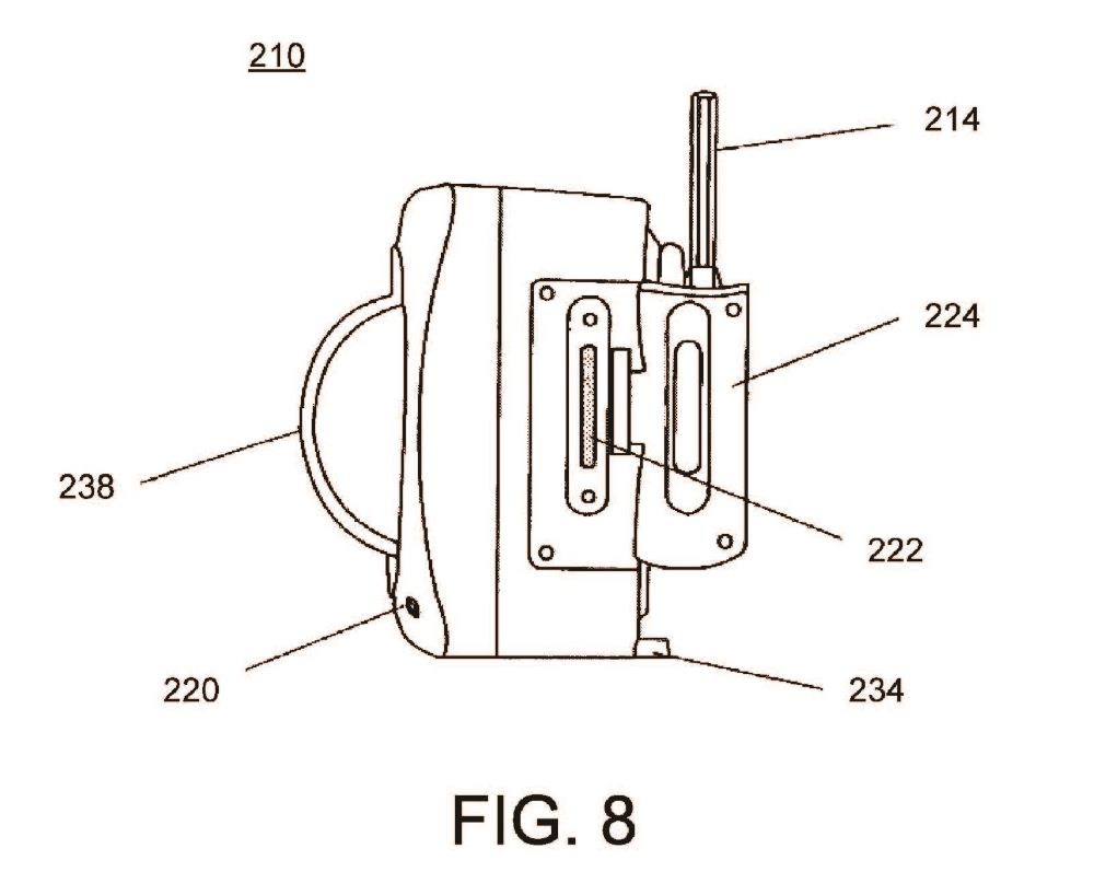
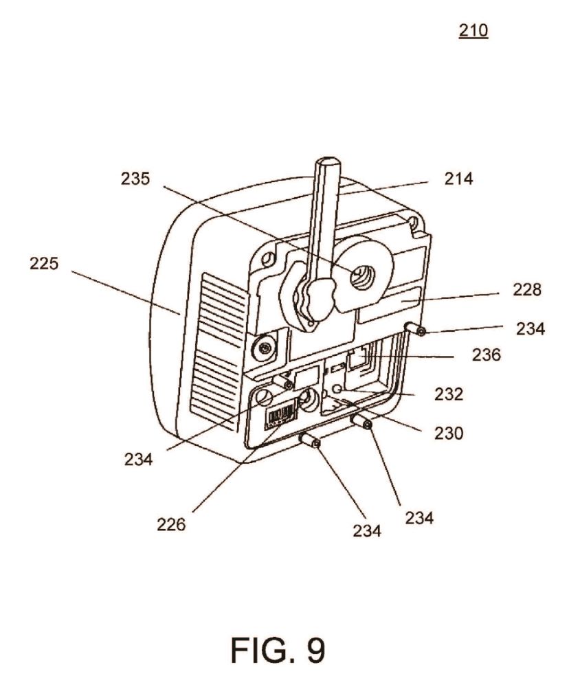
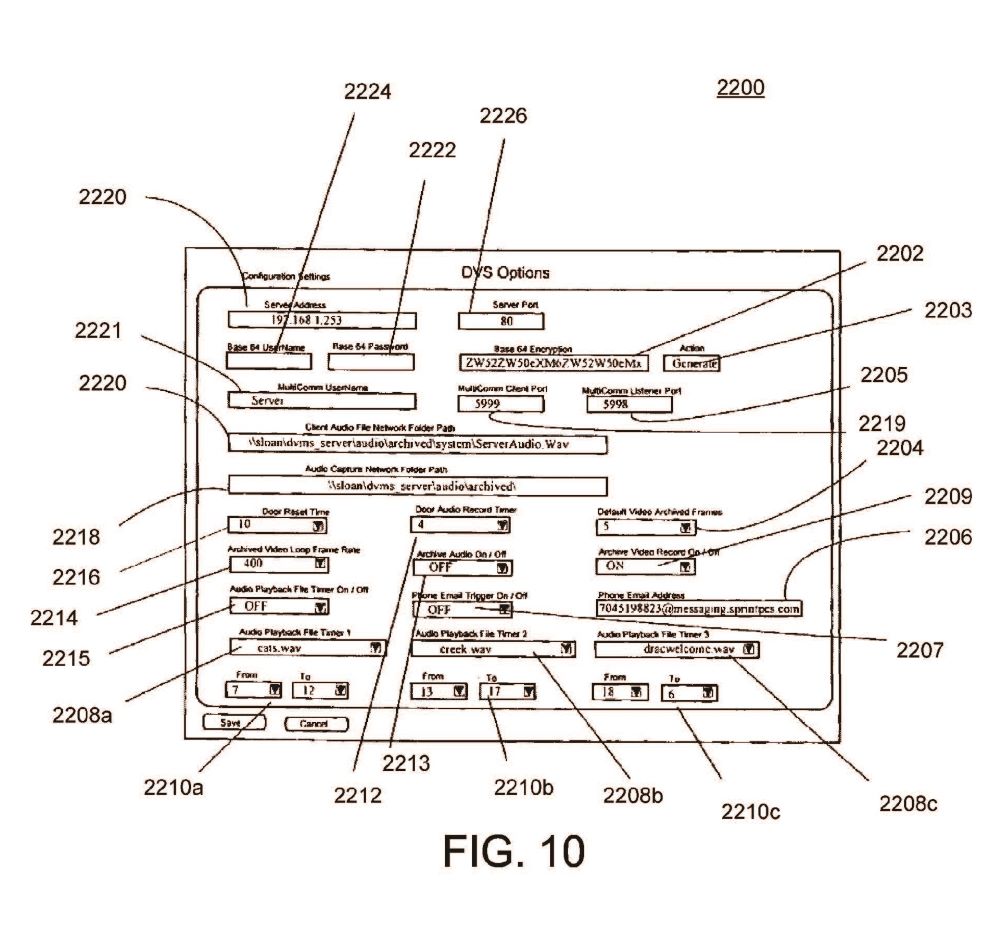
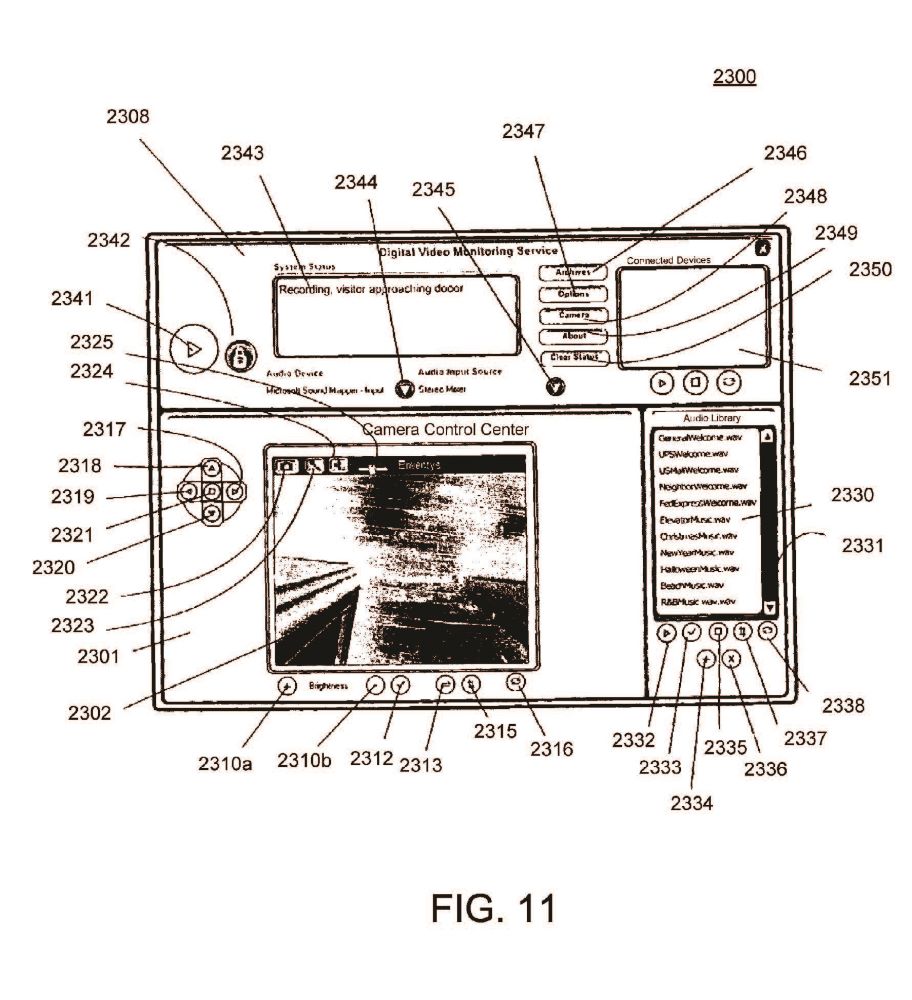
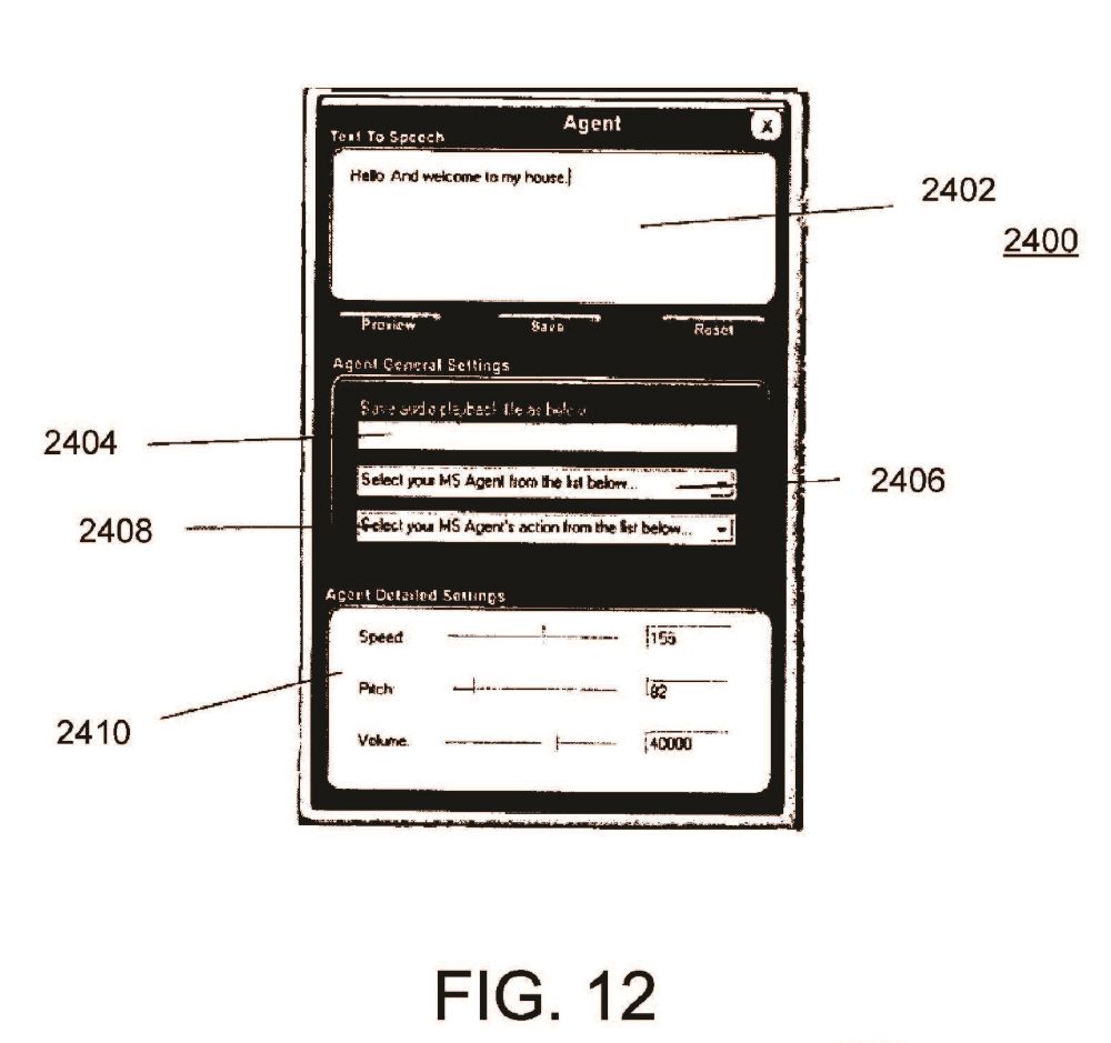

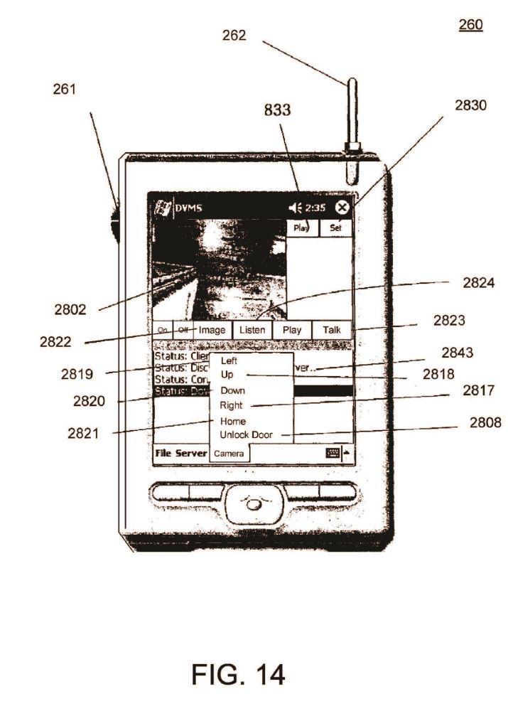
ABSTRACT
A method for two-way audio-video communications between a first person at an entrance and a second person comprises the steps of detecting, with a proximity sensor located proximate an entrance, the presence of a first person at the entrance and providing real time audio-video communications between the first person at the entrance and a second person using a wireless handheld device. The method includes transmitting video of the first person to the wireless handheld device of the second person, transmitting audio of the first person to the wireless handheld device of the second person, and transmitting audio of the second person to the first person at the entrance.
DESCRIPTION
I. CROSS REFERENCE TO RELATED APPLICATION
This application is a continuation-in-part patent application of, and claims the benefit under 35 U.S.C. §120 to, U.S. patent application Ser. No. 10/682,185, filed Oct. 9, 2003, published as U.S. Patent Appl. Publication No. 2005/0285934 A1 and now granted as U.S. Pat. No. 7,193,644, which patent application is a nonprovisional patent application of U.S. patent application Ser. No. 60/418,384, filed on Oct. 15, 2002, expired. Each of these patent applications, patent application publication, and patent is hereby incorporated herein by reference.
II. BACKGROUND OF THE INVENTION
There are numerous problems presently associated with receiving visitors at a home or office. When the resident of the home or occupant of the office (hereinafter generally referred to as either resident or occupant) is absent, there is often no message for the visitors, no means to leave an interactive message for the resident, and no means to ensure that unwanted access is not obtained. Moreover, answering the call of someone at a door of a dwelling can present certain security risks to an occupant therein. This situation can be especially inconvenient when, for example, a delivery or repair person arrives and the resident is not present. When the resident is present, on the other hand, there are also problems associated with receiving visitors. Some visitors may be unwelcome, for example, and it is often not evident that a visitor is a threat or an annoyance until after the door is open.
There are many types of systems for receiving a person by an occupant or resident and/or on the behalf of the occupant or resident. Such systems include those disclosed in each of: U.S. Pat. No. 5,148,468 titled “Door Answering System”, which issued Sep. 15, 1992 to Marrick et al; U.S. Pat. No. 5,303,300 titled “Security Door Phone Device,” which issued Apr. 12, 1994 to Eckstein; U.S. Pat. No. 5,406,618 titled “Voice Activated, Hands Free Telephone Answering Device,” which issued Apr. 11, 1995 to Knuth, et al.; and U.S. Pat. No. 5,657,380 titled “Interactive Door Answering and Messaging Device with Speech Synthesis,” which issued to Mozer on Aug. 12, 1997. Nevertheless, a need remains for further improvement in such a system.
III. SUMMARY OF THE INVENTION
The invention includes many aspects and features. Moreover, while many aspects and features of the invention relate to, and are described in, the context of a system for receiving a person at an entrance, such as, an entrance to a home or business, the invention is not limited to use only in such context and may be used and has applicability in other contexts as well.
In one aspect of the invention, an audio-video communication system comprises a wireless exterior module located proximate an entrance, a computerized controller running a software application and a remote peripheral device. The wireless exterior module includes a proximity sensor for detecting a person at the entrance, a video camera for recording an image of the person at the entrance, a microphone for recording sound of the person at the entrance, a speaker for playing audio to the person at the entrance, a transmitter for communicating sounds and images of the person at the entrance, and a receiver for receiving communications at the wireless exterior module. The computerized controller is disposed in wireless electronic communication with the wireless exterior module via the transmitter and the receiver of the wireless exterior module. The computerized controller is configured to control recording of communications with the wireless exterior module and playback of such recording, and the software application includes a graphic user interface that enables a user to view images from the video camera communicated from the wireless exterior module. The remote peripheral device is configured to electronically communicate with the computerized controller for viewing an image from the video camera communicated from the wireless exterior module.
In a feature of the first aspect, the audio-video communication system further comprises a second wireless exterior module located proximate an entrance, with the second wireless exterior module having a proximity sensor for detecting a person at the entrance, a video camera for recording an image of the person at the entrance, a microphone for recording sound of the person at the entrance, a speaker for playing audio to the person at the entrance, a transmitter for communicating sounds and images of the person at the entrance, and a receiver for receiving communications at the wireless exterior module. The computerized controller running the software application is further disposed in wireless electronic communication with the second wireless exterior module via the transmitter and the receiver of the second wireless exterior module.
In another feature of this aspect, the remote peripheral device is configured to remotely actuate the camera of the wireless exterior module. In an additional feature, the graphic user interface enables a user to view streaming video with the remote peripheral device. In yet another feature, the remote peripheral device comprises a cell phone. In still yet another feature, the remote peripheral device comprises a video phone. In further features, the remote peripheral device comprises a computer and a personal digital assistant.
In an additional feature, the entrance comprises an entrance of a business. In another additional feature, the entrance comprises an entrance of a residence. In a further feature, the wireless exterior module includes a display screen. In still a further feature, the wireless exterior module includes a keypad comprising a touch screen or a keyboard. In yet a further feature, the wireless exterior module is portable and includes a locking mechanism and an electrical receptacle for quickly attaching to a source of electricity.
In another feature, the wireless exterior module has a portable energy source and is secured in a holster. In yet another feature, the computerized controller comprises a personal computer. In still yet another feature, the computerized controller is disposed in electronic communication with a public switching telephone network (PSTN).
In a further feature, the computerized controller is disposed in electronic communication with the Internet. In an additional feature, the audio-video communication system further comprises an electronically actuated lock that is configured to be unlocked by the computerized controller. In another feature, the system further comprises a voice recognition system.
In still a further feature, a transceiver includes the transmitter for communicating sounds and images of the person at the entrance and the receiver for receiving communications at the wireless exterior module. In yet another feature, the computerized controller includes an image recognition module for identifying at least one of faces, eyes, and fingerprints.
In a second aspect of the invention, a method for two-way audio-video communications between a first person at an entrance and a second person comprises the steps of (a) detecting, with a proximity sensor located proximate an entrance, the presence of a first person at the entrance; and (b) providing real time audio-video communications between the first person at the entrance and a second person using a wireless handheld device. Step (b) is done by (i) transmitting, to the wireless handheld device of the second person, video of the first person at the entrance recorded using a camera located proximate the entrance, (ii) transmitting, to the wireless handheld device of the second person, audio of the first person at the entrance recorded using a microphone located proximate the entrance, and (iii) transmitting, to a speaker located proximate the entrance for playing to the first person at the entrance, audio of the second person recorded using the wireless handheld device.
In a feature of this aspect, the transmitting includes wireless communications between both the camera and microphone located proximate the entrance and a computerized controller running a software application including a graphic user interface by which the audio-video communications between the first person and the second person are established. In another feature, the method further comprises the step of playing a recorded greeting to the first person at the entrance upon the detection of the first person at the entrance with the proximity sensor. With regard to this feature, the method further comprises determining, by a user with a remote peripheral device, the recorded greeting that is played through a graphical user interface. With further regard to this feature, the recorded greeting is selected by the user from a plurality of recorded greetings. It accordance with this feature, the recorded greetings are seasonal greetings. It is preferred that the recorded greeting includes audio and video.
In an additional feature, the method further comprises the step of posting, by the user from a remote peripheral device, a video greeting for presentation to a first person at the entrance. In further features, the wireless handheld device comprises a cell phone, a video phone, and a personal digital assistant.
In yet another feature, the entrance comprises an entrance of a business. In still a further feature, the entrance comprises an entrance of a residence. In another feature, the method further comprises the step of saving a recording of the two-way audio-communications in a database for later playback. In yet another feature, the method further comprises transmitting, to a video display located proximate the entrance for presentation to the first person at the entrance, video of the second person recorded using the wireless handheld device.
In an additional feature, the transmitting includes communications over the Internet. In further features, the transmitting includes communications over a cellular network and over a satellite network. In yet another feature, the method further comprises remotely actuating the camera located proximate the entrance using the wireless handheld device. In still further features, the step of remotely actuating the camera includes zooming an image of the first person at the entrance and remotely moving the camera to change the view of the camera.
In a third aspect of the invention, a method for receiving a person at an entrance comprises the steps of (a) detecting, with a proximity sensor located proximate an entrance, the presence of a person at the entrance; (b) transmitting, to a computerized controller running a software application, video of the person at the entrance recorded using a camera located proximate the entrance; and (c) providing, with the application software running at the computerized controller, a graphic user interface to a remote peripheral device by which a user of the remote peripheral device may view the video of the person at the entrance.
In a feature of this aspect, the method further comprises the step of saving, in accordance with the application software running at the computerized controller, the video of the person at the entrance in a database in association with a timestamp. In other features, the video is viewed using the remote peripheral device in real-time, viewed using the remote peripheral device after the person at the entrance has left, and is streamed to the remote peripheral device.
In an additional feature, the method further comprises the step of transmitting, to the computerized controller running the software application, audio of the person at the entrance recorded using a microphone located proximate the entrance; wherein the graphic user interface provided to the remote peripheral device further enables a user of the remote peripheral device to hear the audio of the person at the entrance. In another feature, the method further comprises the step of playing a recorded greeting to the person at the entrance upon the detection of the person at the entrance with the proximity sensor.
In another feature, the method further comprises determining, by a user with the remote peripheral device, the recorded greeting that is played through a graphical user interface. With regard to this feature, the recorded greeting may be selected by the user from a plurality of recorded greetings, the recorded greetings may be seasonal greetings, and the recorded greeting may include audio and video.
In yet another feature, the method further comprises the step of posting, by the user from the remote peripheral device, a video greeting for presentation to a person at the entrance. In other features, the remote peripheral device comprises a cell phone, a video phone, a computer, and a personal digital assistant. In still other features, the entrance comprises an entrance of a business and an entrance of a residence.
In still another feature, the method further comprises remotely actuating the camera located proximate the entrance using the remote peripheral device. In further features, the step of remotely actuating the camera includes zooming an image of the person at the entrance and remotely moving the camera to change the view of the camera.
In addition to the aforementioned aspects and features of the present invention, it should be noted that the present invention further encompasses the various possible combinations of such aspects and features.
IV. BRIEF DESCRIPTION OF THE DRAWINGSOne or more preferred embodiments of the invention now will be described in detail with reference to the accompanying drawings.
FIG. 1 is a schematic diagram of a system in accordance with a preferred embodiment of the invention.
FIG. 2 is a planar view of the font of a DVMS module of the system of FIG. 1
FIG. 3 is a planar view of the front of a DVMS transceiver of the system of FIG. 1.
FIG. 4 is a block diagram overview of a method in accordance with a preferred embodiment of the invention.
FIG. 5 a block diagram extension of the method of FIG. 4.
FIG. 6 is a schematic diagram of a system in accordance with another preferred embodiment of the invention.
FIG. 7 is a perspective view of the front of a wireless network camera of the system of FIG. 6.
FIG. 8 is a side view of the wireless network camera of FIG. 7.
FIG. 9 is a perspective view of the rear of the wireless network camera of FIG. 7.
FIG. 10 is a representative screen view of a wireless command center of the system of FIG. 6, wherein various parameter settings for configuring, e.g., the audio, video, server, and cell phone options are illustrated.
FIG. 11 is a screen view of the normal operating mode interface of the wireless command center of FIG. 10, wherein a user is able to dynamically control a wireless network camera, view video images generated by the wireless network camera, listen and send both pre-canned and live audio files, and review archived system events.
FIG. 12 is a dialog box screen view of the text-to-voice synthesizer module of the wireless command center of FIG. 10.
FIG. 13 is a dialog box screen view of the recorded voice synthesizer module of the wireless command center of FIG. 10.
FIG. 14 is a planar view of the front of a wireless pocket PC that is connected to a wireless network, wherein a user of the wireless pocket PC is able to dynamically control the wireless network camera, view video images generated by the wireless network camera, listen and send both pre-canned and live audio files, and review archived system events in the system of FIG. 6.
V. DETAILED DESCRIPTION
As a preliminary matter, it will readily be understood by one having ordinary skill in the relevant art (“Ordinary Artisan”) that the present invention has broad utility and application. Furthermore, any embodiment discussed and identified as being “preferred” is considered to be part of a best mode contemplated for carrying out the present invention. Other embodiments also may be discussed for additional illustrative purposes in providing a full and enabling disclosure of the present invention. Moreover, many embodiments, such as adaptations, variations, modifications, and equivalent arrangements, will be implicitly disclosed by the embodiments described herein and fall within the scope of the present invention.
Accordingly, while the present invention is described herein in detail in relation to one or more embodiments, it is to be understood that this disclosure is illustrative and exemplary of the present invention, and is made merely for the purposes of providing a full and enabling disclosure of the present invention. The detailed disclosure herein of one or more embodiments is not intended, nor is to be construed, to limit the scope of patent protection afforded the present invention, which scope is to be defined by the claims and the equivalents thereof. It is not intended that the scope of patent protection afforded the present invention be defined by reading into any claim a limitation found herein that does not explicitly appear in the claim itself.
Thus, for example, any sequence(s) and/or temporal order of steps of various processes or methods that are described herein are illustrative and not restrictive. Accordingly, it should be understood that, although steps of various processes or methods may be shown and described as being in a sequence or temporal order, the steps of any such processes or methods are not limited to being carried out in any particular sequence or order, absent an indication otherwise. Indeed, the steps in such processes or methods generally may be carried out in various different sequences and orders while still falling within the scope of the present invention. Accordingly, it is intended that the scope of patent protection afforded the present invention is to be defined by the appended claims rather than the description set forth herein.
Additionally, it is important to note that each term used herein refers to that which the Ordinary Artisan would understand such term to mean based on the contextual use of such term herein. To the extent that the meaning of a term used herein—as understood by the Ordinary Artisan based on the contextual use of such term—differs in any way from any particular dictionary definition of such term, it is intended that the meaning of the term as understood by the Ordinary Artisan should prevail.
Furthermore, it is important to note that, as used herein, “a” and “an” each generally denotes “at least one,” but does not exclude a plurality unless the contextual use dictates otherwise. Thus, reference to “a picnic basket having an apple” describes “a picnic basket having at least one apple” as well as “a picnic basket having apples.” In contrast, reference to “a picnic basket having a single apple” describes “a picnic basket having only one apple.”
When used herein to join a list of items, “or” denotes “at least one of the items,” but does not exclude a plurality of items of the list. Thus, reference to “a picnic basket having cheese or crackers” describes “a picnic basket having cheese without crackers”, “a picnic basket having crackers without cheese”, and “a picnic basket having both cheese and crackers.” Finally, when used herein to join a list of items, “and” denotes “all of the items of the list.” Thus, reference to “a picnic basket having cheese and crackers” describes “a picnic basket having cheese, wherein the picnic basket further has crackers,” as well as describes “a picnic basket having crackers, wherein the picnic basket further has cheese.”
Referring now to the drawings, one or more preferred embodiments of the present invention are next described. The following description of one or more preferred embodiments is merely exemplary in nature and is in no way intended to limit the invention, its applications, or uses.
The System of FIG. 1
FIG. 1 is a schematic diagram of a system 100 in accordance with a preferred embodiment of the invention. For purposes of providing an enabling description, the system 100 is described in the context of a door answering system for receiving a person at a home or office and is capable of controlling access to the home or office. In FIG. 1, the exterior of the home or office is differentiated from the interior by demarcation line 115, which represents a wall or other similar structure. The wall 115 includes an entrance in the form of a door 114 and an electronically actuated lock 116 for selectively locking and unlocking the door 114.
A computerized controller in the form of a personal computer 80 is disposed in the interior and is configured to selectively actuate the lock 116. The personal computer 80 preferably includes a DVD-R/W 84, a CD-ROM R/W 92, and a hard drive 86. One or more of these components 84,92,86 of the personal computer 80 preferably are utilized for recording video and audio communications that are transmitted to and from the DVMS module 10 (described in further detail below) and for playing video and audio communications that are stored via the personal computer 80.
The personal computer 80 also may include a voice generator 90 for use in generating prompts, which either exists as pre-recorded messages or are generated by a voice synthesizer. Each of these components 84,92,86,90 of the personal computer 80 may be separately disposed from the personal computer and connected, for example, by a switch 88, or may form part of the personal computer 80 and be disposed in electronic communication with a bus of the personal computer 80 within the housing thereof.
A speaker 44 is disposed in electronic communication with the personal computer 80. The speaker 44 is not shown as being wireless, but could be. Moreover, one speaker 44 is shown, but additional speakers could be used in the system 100. Furthermore, speaker 44 in FIG. 1 is represented as being separate from the personal computer 80, however, the speaker 44 could alternatively form part of the personal computer 80.
The personal computer 80 preferably is disposed in electronic communication with the Internet. The connection with the Internet preferably is accomplished by a broadband connection such as a connection 81 provided by a satellite modem, a DSL model, or a cable modem, or any combination thereof.
The personal computer 80 also preferably is connected to a public switching telephone network (PSTN) 70, which enables communication by and with the personal computer 80 via standard telephone lines.
The personal computer 80 preferably has a battery backup as well as a means for detecting a loss in electrical power such that, when electrical power is lost the battery backup will provide sufficient operating time for the personal computer 80 to notify someone responsible for the maintenance of the system that there has been a loss of electricity. Notification of the loss of electricity can be important, since the loss of electrical power can be an indication of a burglary. Additionally, if there is no electricity, then appliances, such as refrigerators, air conditioners, and heaters, cannot function and significant damage can results if the electrical failure goes undetected for a substantial period of time.
The personal computer 80 runs a software application that includes a DVMS Database Application 82 and graphic user interfaces (GUIs). The personal computer 80, in accordance with the software application, controls communication in the system 100, coordinates multiple communication devices in the system 100, and is used to define responses to prompts and events in the system 100. The DVMS Database Application 82 and its uses are described in greater detail below.
The system 100 further includes a wireless router 42 located in the interior. The wireless router 42 in FIG. 1 is represented as being separate from the personal computer 80, however, the wireless router 42 could alternatively form part of the personal computer 80. The wireless router 42 is used to establish a wireless network and is disposed in electronic communication with the personal computer 80.
The system 100 also includes a DVMS module 10 located on the exterior of the home or office proximate the door 114. The DVMS module 10 is configured for use in the exterior of the home or office, which may include outdoor use in external residential or commercial locations. The DVMS module 10 is disposed in wireless communication with the wireless network, including the personal computer 80, via the wireless router 42.
With reference to FIG. 2, the DVMS module 10 preferably includes: a video camera 22; speakers 12; a proximity sensor 26; a microphone 20; an LCD display 16; a quick connect electrical receptacle 24; and a radiofrequency receiver/transmitter represented by antenna 18. The proximity sensor 26 activates the camera 22 upon detection of movement, which in turn relays an image or streaming video to the personal computer 80 where it is saved by the personal computer 80 in a database in association with a timestamp. Operation of the system is described in further detail below.
The DVMS module 10 optionally includes a small portable energy source, such as a battery that is rechargeable via the quick connect electrical receptacle 24, for portable use as well as for use in the event of a power failure.
The LCD display 16 screen preferably is a low energy screen reducing energy consumption. The LCD display 16 preferably comprises a touch screen and can be used to send and receive text similar to a keypad. Alternatively, or in addition thereto, the DVMS module 10 includes a keypad 14. In either case, the DVMS module 10 enables text messaging by a person at the exterior, which in turn enables a private non-audible conversation to be had and eliminates risks of eavesdropping by a passerby.
The DVMS module 10 also includes a locking mechanism 28 for receipt in a mounting holster (not shown). The locking mechanism 28 enables the DVMS module 10 to be installed securely wherever holstered, or to be moved to some other remote location, as desired. The DVMS module 10 thus is portable, much like a cell phone, and can be securely mounted and quickly connected to an electrical source.
It is anticipated that there could be multiple entrances to the home or office and, similarly, multiple DVMS modules similar to DVMS module 10 of FIG. 2 could be utilized, each disposed in wireless communication with the wireless network via the wireless router 42.
The system optional includes one or more DVMS transceivers 60. The DVMS transceivers 60 is configured for use in the interior of the home or office. As illustrated in FIG. 1, a DVMS transceivers 60 may be disposed in wireless communication with the wireless network, including the personal computer 80, and the DVMS module 10, via the wireless router 42. Additionally or alternatively, a DVMS transceivers 60 may be configured to wirelessly communicate directly with the DVMS module 10, thus bypassing communications through the wireless router 42.
With reference to FIG. 3, each DVMS transceiver 60 is portable and, like the DVMS module 10, the DVMS transceiver 60 communicates by short-range radiofrequency transmissions. The DVMS transceiver 60 includes: speakers 62; a microphone 63; an LCD display 66; a quick connect electrical receptacle 65; and a radiofrequency receiver/transmitter represented by antenna 68. The DVMS transceiver 60 optionally includes a small portable energy source, such as a battery that is rechargeable via the quick connect electrical receptacle 65, for portable use as well as for use in the event of a power failure. The DVMS transceiver 60 further includes a mute switch 61, which cuts-off the microphone 63, thus assuring a user of the DVMS transceiver 60 that a visitor can be monitored using the DVMS transceiver 60 without inadvertently sending an audible signal fro the user.
The LCD display 66 screen preferably is a low energy screen reducing energy consumption. The LCD display 66 preferably comprises a touch screen and can be used is used to send and receive text similar to a keypad. Alternatively, or in addition thereto, the DVMS transceiver 60 includes a keypad 64. In either case, the DVMS module 60 enables text messaging by a user of the DVMS transceiver 60 with a person at the exterior using the DVMS module 10, which in turn enables a private non-audible conversation to be had and eliminates risks of eavesdropping by a passerby.
The system 100 further includes one or more remote peripheral devices. Such devices generally include video phones 72; in-car communication systems such as the well known ONSTAR system 74 currently found in GM cars; telephones 76; cell phones 77; personal computers 78; smartphones/personal digital assistants (PDAs) 79; and other similar communication devices. Each remote peripheral device is configured for electronic communication with the personal computer 80 via at least the PSTN connection 70 or the broadband connection 81.
As mentioned above, the personal computer 80 runs a software application that includes a DVMS Database Application 82 and graphic user interfaces (GUIs). The software application is configured and maintained by an administrator, who defines users thereof. The users in the system 100 are referred to as “occupants” reflecting their relation to the home or office.
Preferably, the occupants have various levels of access to the software application, depending on the privileges set by the administrator. The administrator may also set a level of security under which the system is to operate, particularly with respect to connections made using remote peripheral devices.
Other examples of configuration settings of the software application that are determined by the administrator include: aliases for a declared occupant such as, e.g., “Daddy” or “Momma”; passwords to access the software application; access codes to actuate the electronic lock controlled by the computerized controller; a number or other identifier that corresponds to an occupant's name; and at least one telephone number by which an occupant can be reached. The administrator also preferably defines a preferred hierarchy of storage of audio and video data, the location and number of backup devices, and whether replications of the database are to be kept.
Additionally, when setting up the software application, the administrator chooses, inter alia: a prompt for greeting a visitor; chooses an announcement that is to be given over a speaker within the interior when a visitor arrives; a prompt for requesting information from a visitor; a request instructing a visitor as to their choices in leaving a message or contacting a declared user; and the action that is to be performed by the computerized controller based on the input by the visitor.
The administrator also tailors the security/premise monitoring response by, inter alia: designating telephone numbers that the computerized controller calls when, for example, there is a loss of power; and designating telephone emergency numbers (e.g., telephone numbers for the police, the fire department, relatives, private security companies) that the computerized controller calls when an emergency is detected. The computerized controller also conducts self checks to confirm that all the components of the system are operational and keeps a log of the self checks, and the computerized controller preferably calls one or more designated numbers when a self check indicates a failure or otherwise improper operation.
The software application also can be configured to play background music or videos at different times of the year and/or different times of the day to reflect seasonal holidays, birthdays, and events. For instance, on Halloween the administrator may wish to have scary music and howls issuing from the DVMS module for receiving a person at that time. Furthermore, utilizing the computerized controller, the administrator can choose to use default prompts for interacting with a visitor or create customized prompts.
As hardware is added, such as the number of the DVMS modules and DVMS transceivers, the administrator can update both the network to include the additional devices and the computerized controller to accommodate the additional devices.
The software application also is configured to send voice, text, and video messages via email. The administrator can further set up redundant subsystems of the system 100.
The system 100, in use, enables secure and effective monitoring and interacting with a visitor at a residence or business, including, inter alia: the detection of the presence of a visitor at the exterior of the home or office via the proximity sensor 26, the interactive communication with the visitor, whether an occupant is present or absent from the home or office, the enablement of automated entry into the home or office by the visitor, and personalization of the process of receiving a visitor.
An exemplary method of use in the system 100 includes greeting and communicating with visitors of a business or residence. In accordance with the method, the presence of a visitor is detected via the proximity sensor 26 of the DVMS module 10, where the DVMS module 10 is mounted at or near an entrance to the business or residence. Upon the detection of the visitor by the proximity sensor 26, a message is communicated to the personal computer 80 from the DVMS module 10 indicating the detection of a visitor at the entrance. A recording is actuated by the personal computer 80, and the recording is stored in a computer-readable medium such as a database along with a beginning time-stamp. The arrival of a visitor is broadcast over a speaker within the home or office, such as speaker 44. An occupant can view the visitor on a display on the DVMS transceiver 60 or on a display of the personal computer 80, and the occupant can initiate a conversation at any time. The DVMS module 10 issues a greeting to the visitor and instructs the visitor to select a number from the keypad 14 of the DVMS module 10 in order to designate the occupant being visited. The entered number is communicated from the DVMS module 10 to the personal computer 80, where the software application confirms that the number corresponds to an occupant “y” who is “officially” present. An error message is generated if no individual corresponds to the number entered by the visitor. If no individual corresponds to the number entered by the visitor, then the visitor is prompted to select and press another number on the keypad 14 again designating the occupant being visited. The method then lists the choices again.
While this is going on, the door may be answered at any time, thereby resetting the software application to look for another visitor. The software application keeps track of the number of times a wrong number is entered and can generate a variety of responses to pranks, including calling the police, issuing warnings and/or a loud noise, or just thanking the visitor and asking him to return another time.
If appropriate, when the number designated by the visitor matches an occupant who is officially on the home or office, the speaker broadcasts that the visitor is here to see occupant “y”. Occupant “y” can signal the personal computer 80 to take a message, or occupant “y” may choose to use the DVMS transceiver 60 to speak directly with the visitor, or occupant “y” can answer the door.
If appropriate, the DVMS module 10 issues a prompt stating that occupant “y” is not available and asks the visitor if they wish to speak to occupant “y” or to leave a message.
If appropriate, at any time the software application can initiate a call to occupant “y” via a remote peripheral device for communication between occupant “y” and the visitor, and the software application can record both sides of the conversation between occupant “y” and the visitor. The occupant can view the visitor or initiate a conversation, as the occupant desires. A visitor never knows where the occupant is, unless the occupant tells the visitor of the occupant's location. A visitor also never knows if the occupant can be contacted, or if the occupant has just instructed the application to take a message. Using the method the conversation or messages can be relayed to the selected occupant without the visitor ever knowing where the location of the occupant. Only the occupant can disclose such location to the visitor as desired.
If the visitor elects to leave a message, then the method prompts the visitor to begin his message and then, optionally, offers him a chance to review and approve his message. The message or call is stored in computer readable medium, such as database, by the personal computer 80 in association with a beginning timestamp and an ending timestamp along with the occupant's mailbox number. At the end of the call or message, the software application can issue a closing statement and return to background music, if programmed to do so.
When the visitor departs, and is out of the range of the proximity sensor 26, all recording is stopped and saved in the database record, along with an ending timestamp. The occupant “y” can selectively sort to view the entire recorded visit, or just the message.
If the proximity sensor 26 indicates that there is another visitor, the method cycles back to the greeting step.
If the system has an electronically actuated lock, then the method also may include the steps of checking the number entered by the visitor to determine if it is a valid access code. The electronically actuated lock may be unlocked by entering an access code either at the DVMS module 10 or remotely therefrom. If the number is valid, then the lock is actuated, and if the number is not valid, then a prompt is made requested that the code be re-entered. Optionally, the prompt may further request a number be entered that corresponds to one of the occupants if assistance is needed and, if an occupant is selected, then calling the selected occupant. The method also may include tracking how many times the wrong code is entered; checking if the maximum allowed number of wrong entries have been made; and, when the maximum number of wrong entries is reached, either automatically calling a designated party and/or removing access privileges.
An occupant preferably has the option of remotely entering the access code, thereby actuating the electronically actuated lock, or instructing the GUI database application to go to a new high security level, wherein the lock cannot be accessed and notifying the visitor that the access code is not operational.
In the method, upon the entering of a valid access code assigned to a declared occupant, the software application optionally notifies the administrator or his designated representative that the declared occupant has now entered the home or office. The administrator would know who the individual should be. The administrator thus can confirm, by remotely viewing the recorded video, that the actual person who entered the access code is the declared occupant, and/or make a follow-up telephone call to the home or office. The system 100 also provides the options of allowing the visitor to converse with the occupant, leaving a message, or calling a remote peripheral device for communication with the occupant when he is either not present or is unavailable. The entrance is recorded and time stamped for sorting or viewing either in real time or at a later date.
The system 100 further enables the administrator or a declared occupant to, at any time, to turn on a camera and view images, access the recorded the video images, or post a video image from a remote peripheral device to computerized controller including associated components.
The system 100 preferably is inherently extensible in both form and function and is designed so that the system can be expanded to include multiple peripheral devices, both in direct and indirect communication with the computerized controller. Due to the use of the computerized controller and its interconnectivity, the disclosed system 100 can be configured to accommodate communications having a range of complexity.
As will be apparent from the foregoing, the system 100 provides an audio-video communication and answering system that provides real time communication between an exterior of a business or residence and an interior of the business or residence as well as a location remotely located to the business or residence.
As will be apparent from the foregoing, the system 100 provides an audio-video communication and answering system that provides real time communication between two or more rooms at a home or office and a remote location.
As will be apparent from the foregoing, the system 100 provides an audio-video communication and answering system that provides the ability to leave messages at a centralized location from a local or remote location.
In addition to the foregoing description of a method, FIG. 4 shows a block diagram illustrating an example of the use of a system of the invention as a door answering and messaging system at a residence. Furthermore, FIG. 5 shows a block diagram illustrating an example of the use of a system of the invention as a door answering and messaging system at a residence, wherein the system includes an electronically actuated lock. In the example, an occupant is attempting to gain access to the home or office.
As will now be apparent, systems in accordance with the invention achieve one or more of the foregoing benefits and features yet remain intuitive and easy to use.
In addition to the foregoing, it further is anticipated that, in certain deployments of the invention, voice recognition would be useful, particularly when the system enables access to a home or office. Voice recognition adds another layer of security, and can be used to facilitate those individuals who are unable to press a keypad. Similarly, image recognition of faces, eyes and fingerprints can also be included in the system for authentication, security, and access. The software application thus alternatively utilizes voice recognition and/or image recognition.
Furthermore, while no camera is shown located within the home or office, any number of cameras could be utilized on the interior.
It will also be appreciated that a business may be a tenant located within a building shared by other businesses. A DVMS module for the business thus would be utilized on the exterior of the business, i.e., at the “front door” of the business, which would be located within the interior of the common building.
In variations of systems of the invention, it should further be noted that one or more devices having the functionality of DVMS modules could be utilized in the interior for securing entrance to a room or group of rooms.
The System of FIG. 6
FIG. 6 is a schematic diagram of a system 2100 in accordance with another preferred embodiment of the invention. The system 2100 includes: a local area network 2200; a wireless digital camera 210; and a computerized controller in the form of a personal computer 240 (identified as the “Wireless Command Computer” in FIG. 6). The lines indicate communications between member devices and components of the system 2100 and such communications may be wired, wireless, or a combination of both wired and wireless. For purposes of providing an enabling description, the system 2100 is described in the context of a door answering system for receiving a person at a home or office and is capable of controlling access to the home or office. In FIG. 6, the exterior of the home or office is differentiated from the interior by a wall 2112 or other similar structure. The wall 2112 includes an entrance in the form of a door 2116 and an electronically actuated lock 2114 for selectively locking and unlocking the door 2116.
The personal computer 240 is disposed in the interior and is configured to selectively actuate the lock 2114. The personal computer 240 includes one or more components utilized for recording video and audio communications and for playing video and audio communications. The personal computer 240 also may include a voice generator for use in generating prompts, which either exists as pre-recorded messages or is generated by a voice synthesizer. Each of these components of the personal computer 240 may be separately disposed from the personal computer and connected, for example, by a switch, or may form part of the personal computer 240 and be disposed in electronic communication with a bus of the personal computer 240 within the housing thereof. A speaker 248 is disposed in electronic communication with the personal computer 240. Moreover, one speaker 248 is shown, but additional speakers could be used in the system 2100. Furthermore, speaker 248 in FIG. 6 is represented as being separate from the personal computer 240, however, the speaker 248 could alternatively form part of the personal computer 240.
The personal computer 240 preferably is disposed in electronic communication with the Internet. The connection with the Internet preferably is provided by a broadband connection through, for example, a wireless router 250. Such broadband connection may be accomplished by a satellite modem, a DSL model, or a cable modem, or any combination thereof. The personal computer 240 also preferably is connected to a public switching telephone network (PSTN) 70, which enables communication by and with the personal computer 240 via standard telephone lines.
The personal computer 240 preferably has a battery backup as well as a means for detecting a loss in electrical power such that, when electrical power is lost the battery backup will provide sufficient operating time for the personal computer 240 to notify someone responsible for the maintenance of the system that there has been a loss of electricity. Notification of the loss of electricity can be important, since the loss of electrical power can be an indication of a burglary. Additionally, if there is no electricity, then appliances, such as refrigerators, air conditioners, and heaters, cannot function and significant damage can results if the electrical failure goes undetected for a substantial period of time.
With regard to the wireless router 250, it is represented as being separate from the personal computer 240, however, the wireless router 42 could alternatively form part of the personal computer 240. The wireless router 42 is used, inter alia, to establish a wireless network and is disposed in electronic communication with the personal computer 240. The router 250 is WiFi compliant, and operates using a standardized protocol such as, for example, 802.11(b) and/or 802.11(g).
The wireless router 250 facilitates two-way communication over the local area network 2200 among the member devices and components of the wireless network 2200. Furthermore, the wireless router 250 preferably is disposed in electronic communication with the Internet and facilitates two-way communication between the member devices and components of the wireless network 2200 and remote devices communicating over the Internet. Such remote devices generally include video phones 275; in-car communication systems, such as the well known ONSTAR system 274 currently found in GM cars; telephones 276; cell phones 277; personal computers 278; smartphones/personal digital assistants (PDAs) 279; and other similar communication devices. Each remote device preferably is configured for electronic communication with one or more of the member devices and components of the wireless network 2200 via at least the PSTN connection 270 or a broadband Internet connection. Additionally, a remote device may be configured to communicate with one or more of the member devices and components of the wireless network 2200 via direct wireless communications with the wireless router 250 when such remote device is within communications range of the wireless router 250. Such direct wireless communications with the wireless router 250 is illustrated with the cell phone 277 in FIG. 6.
The wireless command computer includes a digital video system application (“DVS App”) 242 and a monitoring application 244. The DVS App 242 provides a set of customizable operating parameters for the wireless digital camera 210. The set of digital video operating parameters may include parameters selected from the group of: a default camera position; a number of frames per second; sensitivity and threshold of a motion sensor; length of a session; frequency of motion detection; and sensitivity and threshold of the motion detector. These parameters are conveyed to the camera operation application, discussed in further detail below. The monitoring application 244 includes a camera control screen that displays the camera webpage; and an operating screen that displays a set of operating parameters. The set of operating parameters may include parameters selected from the group of: a card file for cross-referencing MAC ID'S with cameras and pocket PCs on the wireless network; paths for logging and archiving files received from the camera; camera webpage addresses; email addresses for users; telephone numbers for cell phones; a designated greeting when a motion sensor is triggered; and security parameters. The monitoring application 244 further includes an audio library screen that displays the contents of a library of pre-recorded audio files. Typically, at least one pre-recorded audio file is a greeting audio file. In the context of the system 2100, the audio file can be sent over the local area network 2200, and can include, for instance, sounds, music, voice recordings, synthesized noises, and the like. The means of generating an audio file can be a microphone that feeds to an AID converter, which creates a digital audio file, such as a wav file or MP3 file, or a voice synthesized digital audio file. The monitoring application 244 generally includes a means of generating an audio file, and a command computer website that provides a command webpage with graphic controls for reviewing archived files. The monitoring application can further include a set of monitoring parameters that define the criteria for keeping or deleting a video file in memory, wherein the criteria includes available memory on system, age of file, and priority. The monitoring application also can further include an option to designate that the digital camera transmit video and audio data to more than one member device of the wireless network, and/or to split up audio and video data to two or more member devices. This feature is desirable if, for instance, it is preferred that either audio or video not be sent, or if a network member device—for instance a cell phone—is not configured to process both audio and video data. The monitoring application 244 also can include settings for notifying one or more designated individuals or a security service if an alarm is activated or if a predetermined condition is otherwise detected by a sensor. Such sensors may include, for example, smoke detectors, carbon monoxide detectors, laser beam detectors, broken window detectors, temperature detectors, radiation detectors, radon detectors, open window, door detectors, or a combination thereof. Moreover, such sensors may communicate via the local area network 2200.
The system 2100 includes a wireless digital camera 210 located on the exterior of the home or office proximate the door 2116. The wireless digital camera 210 includes a website application 246 and a camera operation application 247. The wireless digital camera 210 is shown in further detail in FIGS. 7-9. The wireless digital camera 210 preferably creates a series of images that are stored as a series of jpeg files which are displayed on a webpage of a website application 246 that is unique to a given camera 210. The camera 210 also includes a microphone 218, and the sound recorded by the microphone is digitized as an audio file, such as a .wav file or an MP3 file, that is transmitted along with the video as an audio file. This camera 210 preferably has a splash resistant body 225, a lens cover 238 over lens 216, and a wireless transceiver for audio 2-way audio communication. Furthermore, this camera 210 can pan, tilt, or move to a pre-set position. The camera 210 includes a motion sensor that triggers video recording with surveillance image quality, refreshing its image 30 frames per second, and includes a charge coupled device sensor to compensate for low light conditions. Communications via the wireless camera 210 also preferably are encrypted. The splash resistant body 225 allows the camera 210 to be used indoors or outdoors. The camera 210 also supports IPv6 (Internet Protocol Version 6). The audio feature of the camera 210 uses a Java applet that is installed during the installation. The camera 210 has a memory card 222 that is protected by a sealing door 224, a proximity detector or motion sensor 220, a microphone 218, a power input 226, an external microphone port 230, a LAN port 236, and a speaker port 232. The illustrated camera 210 has four mounting legs 234 and a mounting stand hole 235. The antenna 214 projects from the rear of the camera. A suitable wireless digital camera that has weather resistance is the camera currently sold in the United States by Panasonic under the part number BB-HCM371.
Every camera in the system 2100 preferably can be uniquely identified by a media access control (MAC) address that enables the personal computer 240, and each device in the system 2100 having a web browser, such as, e.g., a Windows Internet Explorer browser, or a Firefox browser, to be in wireless communication with camera 210 through the wireless router 250. While only one camera 210 is shown in FIG. 6, multiple cameras can be included in the system 2100, each with its own unique website accessible by multiple devices in the system 2100 having Internet browsers. In addition to displaying the video and audio on the camera's webpage, the website application 246 of the camera 210 displays graphic controls for actuating the camera 210, such as panning right and left, up and down, zoom in and zoom out, and adjustments for the amount of ambient light. These controls are illustrated in FIG. 11.
As previously stated, the camera 210 has a motion sensor 220 for detecting the presence of a person or a moving object with an adjustable level of sensitivity and a trigger threshold for initiating video recording, and, optionally issuing a verbal response, such as a greeting. The verbal response is an audio file, which can reside in the camera's memory as well as in the personal computer, in which case the verbal response can be transmitted, via the local area network 2200, to the camera 210. The camera 210 typically has a pre-set or default position, which can be static or dynamic. For instance, the camera 210 can be programmed to pan back and forth through a pre-set cycle or to zoom in and out, or any combination thereof. The motion sensor 220 has parameters for setting the sensitivity and a trigger threshold for initiating video recording. Upon initiation, the camera automatically starts recording video, which is displayed on the camera webpage in the form of video images, typically in serial form. The recording further can be transmitted to the personal computer 240 for saving for later viewing. In an alternative embodiment, the camera does not include a motion sensor 220 in the form of an additional piece of hardware but, instead, detects motion via a software application that analyzes the video images. In this alternative, the camera 210 records images on a routine basis and, when motion is detected, a video recording is initiated and a verbal response optionally is provided. Such software can be executed at the personal computer 210 or can be executed at the camera 210 and form part of the camera application 247.
The website application 246 of the digital camera 210 provides a webpage with graphic controls for operating the camera and a viewing area for viewing video images. When activate for recording the camera 210 provides digital video images that are displayed on the webpage. The camera 210 can be activated manually or self-activated by the motion sensor 220 that detects the presence of a person or a moving object. The motion sensor 220 has an adjustable level of sensitivity and a trigger threshold for initiating video recording. The camera 210 has a memory cache for saving a designated number or series of transmitted video images. Typically, when activated for video recording, the camera also activates audio recording, which provides audio files on the webpage generated by the digital camera's microphone 218. The camera 210 also includes means including the speaker 218 for playing received audio files.
Referring to FIG. 10, the screen 2200 for setting the parameters of the DVS application 242 is illustrated. Communications over the local area network 2200 between the camera 210 and command computer 240 are established using a MAC address of the camera 210 and/or an IP address 2224 for the camera. The default port 2226 for communications is 80. The camera 210 recognizes an encrypted username and password 2202. The DVS application 242 encrypts the username 2224 and the password 2222, using the generator 2203, resulting in the encrypted version 2202. The hierarchical structure of the member devices of the wireless network is defined in 2220, 2219 and 2205. The command computer 240 designated is named “Server”, as shown in the Username textbox 2221. The client port for uploading audio files 2219 is given as port 5999. An example of a client is a pocket PC 260 or cell phone 277 having a web browser. The listener port 2205 for down loading audio files is port 5998. The camera 210 has access to the audio files in a network-shared folder having a designated path 2220. When a greeting/verbal response is triggered by the motion sensor 220, the file is read from the shared folder 2220. Audio files received by the command computer 240 from the camera 210 are saved in the audio capture folder 2218. The received audio files can be accessed by the client, pocket PC 260, or cell phone 277, as well as the command computer 240. The door reset time 2216 is a parameter that designates the length of time in seconds that must pass after the motion sensor 220 no longer detects a visitor before a recording is stopped. The door audio record timer 2212 is the length of a visitor's message in seconds. The default video archived frames 2209 is the number of images or frames that are saved as an archived file. The archived video file 2216 can be played back at various speeds. The archived video loop frame rate 2216 is in frames per millisecond. Recall that the camera is capable of generating 30 frames, or 30,000 frames per millisecond. This feature 2216 allows the video to be slowed down. If the administrator wishes to cut off archiving audio files, the administrator can select this in box 2213. If the administrator wishes to cut off archiving video files, the administrator can select this in box 2209. The audio files can be turned off completely by using the audio playback parameter 2215. The DVS application 242 can be set to send a message to a cell phone or another computer. The phone email trigger 2207 sets this parameter, and the email address is entered into phone email address parameter 2207. The DVS enables different greetings/verbal responses to issue depending on pre-set criteria. The time of day is one criterion. As shown in FIG. 10, there are three audio files: “cats.wav” 2208 a, “creek.wavn 2208 b and “dracwelcome.wav” 2208 c, each of which will be triggered depending on the time of day. Pairs of boxes 2210 a are set from 7 to 12, text boxes 2210 b are set from 13 to 17, and text boxes 2210 c are set from 18 to 6. At 13 hours, or 1 PM, the greeting switches from “cats.wav” 2208 a to “creek.wavf” 2208 b, and at 6 PM the greeting switches from “creek.wav” 2208 b to “dracwelcome.wav” 2208 c. As will be discussed below, additional options also exist for playing the audio files.
As shown in FIG. 11, the camera's webpage is incorporated as a screen in the monitoring application 244 of the wireless command computer 240. In the screenshot of the monitoring application 2300 of FIG. 11, the lower main screen 2301 displays the camera webpage. The camera webpage is comprised of the streaming video images 2301, an icon 2322 for taking a snapshot, an icon 2323 enabling the user to talk via the camera using the command computer's microphone, an icon 2324 enabling the user to hear sound picked up by the camera's microphone 218, and icon 2325 enabling the user to zoom in and out. Additionally the webpage has graphic controls for remotely positioning the camera, adjusting brightness and automatic panning. The cross-shaped icon on the side has left arrow 2319 for turning the lens left, a right arrow 2317 for turning the lens right, an up arrow 2318 for turning the lens up, a down arrow 2320 for turning the lens down, and a center button 2321, which returns the camera to its default position. On the bottom of the webpage is an icon 2310 a for increasing the brightness when the light is low, and icon 2310 b for decreasing the brightness when the light is high. Icon 2312 sets the brightness to the default position, and icon 2316 is a reset button that returns all parameters to the factory settings. The camera automatically pans back and forth when button 2313 is clicked, and pans up and down when button 2315 is clicked. Panning is stopped by re-clicking the pan icons. The double curved arrow icon 2316 refreshes the camera controls. The audio library screen 2330 contains a list of all the currently recorded audio files. A scroll bar 2331 enables the user to quickly move down the list. To play a selection, a file is selected with the cursor, and then arrow icon 2332 is clicked. The check icon 2333 designates a file as a greeting/verbal response file. The square icon 2334 is the stop button, the plus icon 2335 initiates a module for adding a new audio file, the X icon 2336 deletes a selected audio file, the double arrow icon 2337 causes all checked audio files to be played in random order, and the icon 2338 is a reset button. The top screen 2308 contains a number of options, including starting and running the DVMS service. Large button 2341 turns the program off when clicked, and on when clicked again. Clicking on the lock icon 2342 actuates the door lock. Screen 2343 contains information about what is occurring at the camera, and other system performance information. Drop down icon 2344 opens a dialog box mapping all the sounds and multimedia properties. Drop list icon 2345 displays a list of input devices, such as the microphone on the command computer 240, when talking directly to the camera 210, which needs to be selected to conduct real time conversations. The connected devices screen 2351 displays a list of the wireless network deices, and whether they are currently available. The archives button 2346 activates a screen that lists all the archived video and audio files, and a timestamp for when they were created. The options button 2347 activates the DVS screen 2200 for configuring the application.
The camera has a software package that is run when initializing a new or an addition camera, where communication is established using the MAC address and the subsequent assignment of an IP address. Clicking the camera button 2348 starts that software. The about button 2349 has general information about the version of the DVMS system and contact information. The status button 2350 clears screen 2351.
When recording an audio file, the user can use a synthesizer module or voice recording module. The synthesizer module is a dialog box 2400 shown in FIG. 12, and the voice recording module is a dialog box 2500 shown in FIG. 13. The synthesizer module and the voice recording modules are Microsoft open source modules. In the voice synthesizer module, text is entered into screen 402 and then saved in path 404. An animated character/agent pops up on the command computer when the audio file is played, and characteristics of the agent are selected using screens 2406, 2408, 2410. For instance, a wizard can be selected as the MS Agent, and the wizard flies quickly, and speaks loudly with a low pitch. In FIG. 13, the user can record his or another's voice, or some sound, music, or other audible sound.
The local area network 2200 optionally includes one or more portable devices such as the pocket PC 260 represented in FIG. 6 and shown in detail in FIG. 14. The pocket PC 260 is configured with a client DVMS application. The pocket PC 260 is wireless, having antenna 262 that communicates with the personal computer 240 and the wireless digital camera 210 via wireless modem 250. Similar to the personal computer 240, the pocket PC 260 includes a display screen 2802 for viewing streaming video from the digital camera 210, an “Image” icon 2822 for saving a snapshot, a listen icon 2824 which plays audio from the camera, and a talk icon 2823 for transmitting audio to the camera. The audio volume is adjusted using thumb wheel 261. The pocket PC 260 further includes controls for pointing the camera in the desired direction including: menu selection 2819 for left, menu selection 2818 for up, menu selection 2817 for right, menu selection 2820 for down, and menu selection 2821 to return to the camera 210 the default position. The door lock is unlocked for access using menu selection 2808, which transmits an access code in the form of text to the locking mechanism 2114. The lower screen 2843 displays the status of member devices in the local area network 2200. The library of audio files is accessible through the set button 2830, and the play button 2833 selects the audio file to be played.
While not explicitly shown, it is anticipated that the system 2100 may include voice recognition and image recognition for additional security in authentication and access.
The system provides the options of allowing the visitor to converse with the occupant, leave a message, or call a remote peripheral device for communication with the occupant when he is either not present or unavailable. The visit is recorded and time stamped for sorting or viewing either in real time or at a later date. The system achieves these features, while still presenting a system that is intuitive and easy to use. The digital video monitoring system is extensible, scalable, and flexible in that the number of members of the wireless network can be readily expanded, the system provides and audio and video record of events, and a number of the components are currently off-the-shelf computerized devices that can be configured for the system. Finally, the system allows the users to achieve a high level of security and anonymity.
As will be apparent from the foregoing, the system 2100 enables wireless audio-video communication by all the member devices with each digital camera and the command computer; the system 2100 enables the option of having a visitor converse with an occupant, leave a message, or contact a remote device for communication with a member of the network that is offsite; the system 2100 enables a wireless digital camera to generate and audio and video recording of a visitor upon the sensing that a visitor is proximate the door, with the recording being viewed in real time, or at a later time, either locally or remotely; the system 2100 is highly extensible and can be easily adapted to control many cameras, the images of which can be simultaneously viewed by multiple individuals by merely browsing the individual camera's website that is unique to each camera. The system 2100 also is highly scalable due to the incorporation of a wireless network in the local area network 2200; the system 2100 enables an alarm and or automated calls to designated institutions and individuals when there is a security breach detected; the system 2100 allows users having the proper privileges to remotely permit entrance to a building; the system 2100 can be customized to reflect holidays, special occasions, and various levels of security.
Based on the foregoing description, it will be readily understood by those persons skilled in the art that the invention is susceptible of broad utility and application. Many embodiments and adaptations of the invention other than those specifically described herein, as well as many variations, modifications, and equivalent arrangements, will be apparent from or reasonably suggested by the present invention and the foregoing descriptions thereof, without departing from the substance or scope of the present invention. Accordingly, while the invention has been described herein in detail in relation to one or more preferred embodiments, it is to be understood that this disclosure is only illustrative and exemplary of the invention and is made merely for the purpose of providing a full and enabling disclosure of the invention. The foregoing disclosure is not intended to be construed to limit the present invention or otherwise exclude any such other embodiments, adaptations, variations, modifications or equivalent arrangements, the invention being limited only by the claims appended hereto and the equivalents thereof.
CLAIMS
1. A method for two-way audio-video communications between a first person at an entrance and a second person, comprising the steps of:
(a) detecting the presence of a first person at the entrance; and
(b) following detection of the presence of the first person at the entrance, providing real time audio-video communications between the first person at the entrance and a second person using a wireless handheld device by,
(i) transmitting, to the wireless handheld device of the second person, video of the first person at the entrance recorded using a camera located proximate the entrance,
(ii) transmitting, to the wireless handheld device of the second person, audio of the first person at the entrance recorded using a microphone located proximate the entrance, and
(iii) transmitting, to a speaker located proximate the entrance for playing to the first person at the entrance, audio of the second person recorded using the wireless handheld device.
2. The method of claim 1, wherein said transmitting includes wireless communications between both the camera and microphone located proximate the entrance and a computerized controller running a software application including a graphic user interface by which the audio-video communications between the first person and the second person are established.
3. The method of claim 1, further comprising the step of playing a recorded greeting to the first person at the entrance upon the detection of the first person at the entrance.
4. The method of claim 3, further comprising determining, by a user with a remote peripheral device, the recorded greeting that is played through a graphical user interface.
5. The method of claim 4, wherein the recorded greeting is selected by the user from a plurality of recorded greetings.
6. The method of claim 4, wherein the recorded greetings are seasonal greetings.
7. The method of claim 4, wherein the recorded greeting includes audio and video.
8. The method of claim 1, further comprising the step of posting, by the user from a remote peripheral device, a video greeting for presentation to a first person at the entrance.
9. The method of claim 1, wherein the wireless handheld device comprises a cell phone.
10. The method of claim 1, wherein the wireless handheld comprises a video phone.
11. The method of claim 1, wherein the wireless handheld comprises a personal digital assistant.
12. The method of claim 1, wherein the entrance comprises an entrance of a business or residence.
13. The method of claim 1, further comprising the step of saving a recording of the two-way audio-communications in a database for later playback.
14. The method of claim 1, further comprising transmitting, to a video display located proximate the entrance for presentation to the first person at the entrance, video of the second person recorded using the wireless handheld device.
15. The method of claim 1, wherein said transmitting includes communications over the Internet.
16. The method of claim 1, wherein said transmitting includes communications over a cellular network.
17. The method of claim 1, wherein said transmitting includes communications over a satellite network.
18. The method of claim 1, further comprising remotely actuating the camera located proximate the entrance using the wireless handheld device.
19. The method of claim 18, wherein said step of remotely actuating the camera includes zooming an image of the first person at the entrance.
20. The method of claim 18, wherein said step of remotely actuating the camera includes remotely moving the camera to change the view of the camera.
21. The method of claim 1, wherein said step of detecting the presence of the first person at the entrance is accomplished using a proximity sensor located proximate the entrance.
CITATIONS
| Cited Patent | Filing date | Publication date | Applicant | Title |
|---|---|---|---|---|
| US4804945 | Oct 29, 1987 | Feb 14, 1989 | Millet; Terrance | Door alarm with infrared and capacitive sensors |
| US4931789 | May 12, 1988 | Jun 5, 1990 | Universal Photonix, Inc. | Apparatus and method for a universal electronic locking system |
| US5031228 | Sep 14, 1988 | Jul 9, 1991 | A. C. Nielsen Company | Image recognition system and method |
| US5148468 | Oct 24, 1990 | Sep 15, 1992 | Arnold; Gregory J. | Door answering system |
| US5303300 | Jun 29, 1992 | Apr 12, 1994 | Eckstein; Donald | Security door phone device |
| US5406618 | Oct 5, 1992 | Apr 11, 1995 | Phonemate, Inc. | Voice activated, handsfree telephone answering device |
| US5428388 | Jun 15, 1992 | Jun 27, 1995 | Richard von Bauer | Video doorbell system |
| US5657380 | Sep 27, 1995 | Aug 12, 1997 | Sensory Circuits, Inc. | Interactive door answering and messaging device with speech synthesis |
| US5896165 | Apr 9, 1997 | Apr 20, 1999 | Texas Instruments Incorporated | Method and system for a video answering machine |
| US5966432 | Apr 14, 1997 | Oct 12, 1999 | Nortel Networks Corporation | Remote answering of doorbell |
| US6041106 | Jan 15, 1997 | Mar 21, 2000 | Elite Entry Phone Corp. | Access control apparatus for use with buildings, gated properties and the like |
| US6049598 | Aug 28, 1997 | Apr 11, 2000 | Alcatel | Facility for tying a door intercommunication system with a video camera to an integrated services digital network |
| US6094213 | Apr 13, 1998 | Jul 25, 2000 | Samsung Electronics Co., Ltd. | Computer conference system with video phone connecting function |
| US6185294 | Feb 3, 1998 | Feb 6, 2001 | Chornenky O. Joseph | Method and apparatus for installing telephone intercom-voice messaging apparatus at doorbell for dwelling |
| US6233328 | Apr 1, 1996 | May 15, 2001 | Wolf Michael | Door intercom |
| US6317489 | Dec 12, 1997 | Nov 13, 2001 | Elite Access Systems, Inc. | Entry phone apparatus and method with improved alphabetical access |
| US6324261 | Apr 28, 1998 | Nov 27, 2001 | Merte Donald A. | Door answering machine |
| US6356192 | Aug 27, 1999 | Mar 12, 2002 | Royal Thoughts L.L.C. | Bi-directional wireless detection system |
| US6429893 | Jun 4, 1998 | Aug 6, 2002 | Xin Alfred X. | Security system |
| US6438221 | Sep 8, 1999 | Aug 20, 2002 | Buczek Joseph E. | Electronote wall mounted messaging device |
| US6466261 | Mar 20, 1998 | Oct 15, 2002 | Niles Parts Co, Ltd. | Door camera unit having a video memory |
| US6504470 | Jan 16, 2001 | Jan 7, 2003 | Nextgenid, Ltd. | Access control method and apparatus for members and guests |
| US6509924 | May 3, 2001 | Jan 21, 2003 | Sharp Kabushiki Kaisha | Video telephone with automatic answering function |
| US6759956 | Sep 19, 2001 | Jul 6, 2004 | Royal Thoughts, L.L.C. | Bi-directional wireless detection system |
| US6762788 | May 9, 2002 | Jul 13, 2004 | Tranwo Technology Corp. | Wireless video/audio transmission device for bi-directional communications |
| US6778084 | Jan 9, 2002 | Aug 17, 2004 | Chang Industry, Inc. | Interactive wireless surveillance and security system and associated method |
| US7015943 | Jul 11, 2003 | Mar 21, 2006 | Le, Thi Co | Premises entry security system |
| US7015946 | Apr 12, 2002 | Mar 21, 2006 | Aiphone Co., Ltd. | Television door intercom apparatus |
| US7046268 | Dec 19, 2002 | May 16, 2006 | Kyocera Corporation | Portable videophone unit |
| US7088233 | Jun 7, 2002 | Aug 8, 2006 | Royal Thoughts, Llc | Personal medical device communication system and method |
| US7136458 | Dec 23, 1999 | Nov 14, 2006 | Bellsouth Intellectual Property Corporation | Voice recognition for filtering and announcing message |
| US7162281 | Feb 20, 2003 | Jan 9, 2007 | Kim Dong Joo | Mobile phone holder |
| US7353042 | Aug 22, 2001 | Apr 1, 2008 | Unirec Co., Ltd. | Wireless call system |
| US7583191 | Nov 14, 2006 | Sep 1, 2009 | Zinser Duke W | Security system and method for use of same |
| US7839985 | Apr 13, 2005 | Nov 23, 2010 | Sk Telecom Co., Ltd. | System and method for visitor reception service in absence |
| US20020050932 | Oct 30, 2001 | May 2, 2002 | Ocean Systems Engineering Corporation | Environment and hazard condition monitoring system |
| US20070103542 | Dec 29, 2006 | May 10, 2007 | Revolutionary Concepts, Inc. | Video communication method for receiving person at entrance |
| US20070103548 | Dec 29, 2006 | May 10, 2007 | Revolutionary Concepts, Inc. | Audio-video communication system for receiving person at entrance |
| US20080117299 | Oct 30, 2007 | May 22, 2008 | Revolutionary Concepts, Inc. | Communication and monitoring system |
| US20080136908 | Oct 30, 2007 | Jun 12, 2008 | Revolutionary Concepts, Inc. | Detection and viewing system |
| USD413541 | Jul 23, 1998 | Sep 7, 1999 | Door answering system |
NON-CITATIONS
| Reference | |
|---|---|
| 1 | "3006 Doorphone Trunk Port", publicly accessed via the Internet on May 13, 2002, . |
| 2 | "Doorphone", publicly accessed via the Internet on May 13, 2002, . |
| 3 | "New Invention Provides Security and Convenience", The Cape Fear Messenger, newspaper article published on Mar. 30, 1988. |
| 4 | "Nortel Venture wired phone system", publicly accessed via the Internet on May 13, 2002, . |
| 5 | "Venture Specifications", publicly accessed via the Internet on May 13, 2002, . |
| 6 | "Wireless-G Internet Video Camera-Model No. WVC54G-Send live video and audio to a web browser anywhere in the world!", Linksys a Division of Cisco Systems, Inc. Product Data Sheet, Copyright 2004 Cisco Systems, Inc. |
| 7 | "3006 Doorphone Trunk Port", publicly accessed via the Internet on May 13, 2002, <http://www.algosolutions.com/product/3006.htm>. |
| 8 | "Doorphone", publicly accessed via the Internet on May 13, 2002, <http://www.smarthome.com/images/5079dgmbig.jpg>. |
| 9 | "Nortel Venture wired phone system", publicly accessed via the Internet on May 13, 2002, <http://shop.store.yahoo.com/phonesystem/norvanwirsys.html>. |
| 10 | "Venture Specifications", publicly accessed via the Internet on May 13, 2002, <http://www.gd-wts.com/widts/Vendor%20Info/venture.htm>. |
| 11 | "Wireless-G Internet Video Camera—Model No. WVC54G—Send live video and audio to a web browser anywhere in the world!", Linksys a Division of Cisco Systems, Inc. Product Data Sheet, Copyright 2004 Cisco Systems, Inc. |
REFERENCE BY
FRONT
| Publication number | US8144184 B2 |
| Publication type | Grant |
| Application number | 11/929,412 |
| Publication date | Mar 27, 2012 |
| Filing date | Oct 30, 2007 |
| Priority date | Oct 15, 2002 |
| Also published as | 3 More » |
| Inventors | |
| Original Assignee | |
| U.S. Classification | |
| International Classification | |
| Cooperative Classification | 4 More » |
| European Classification | H04N 7/18D3
4 More » |
| References | |
| External Links | |
DRAWINGS (14)
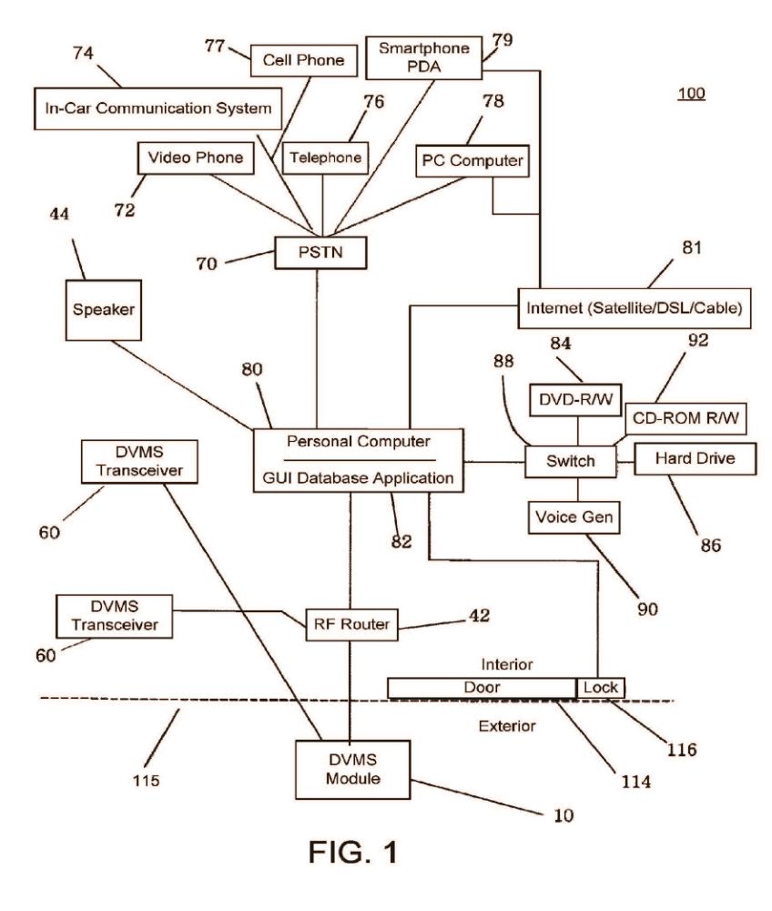
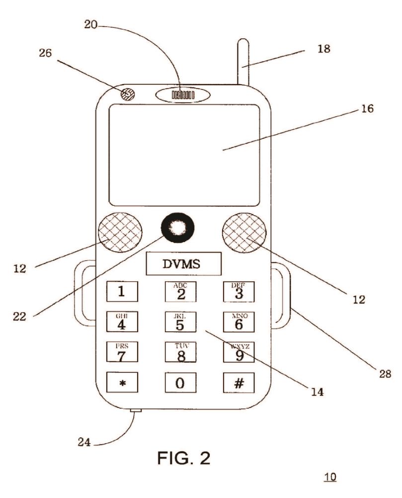


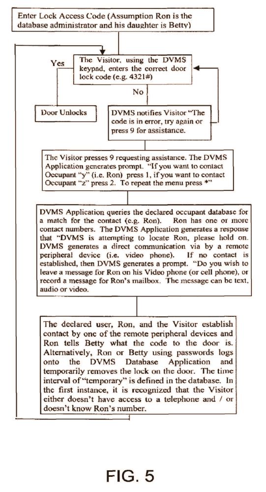
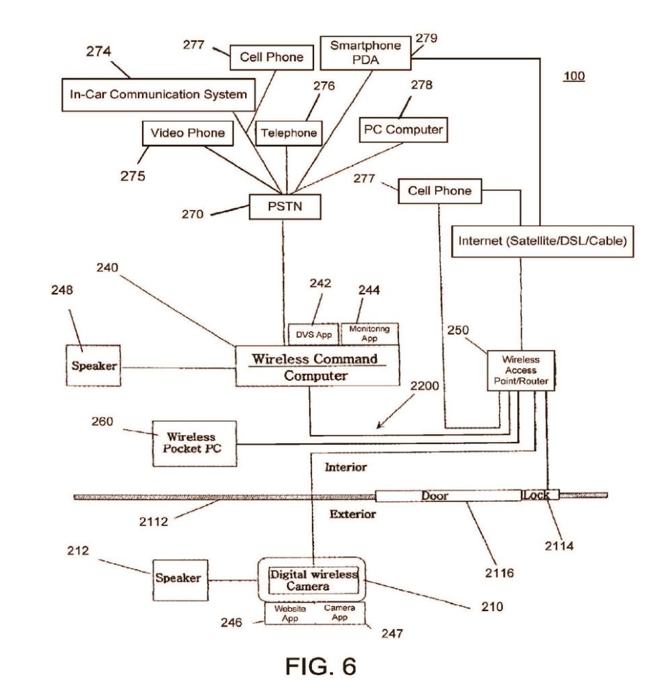
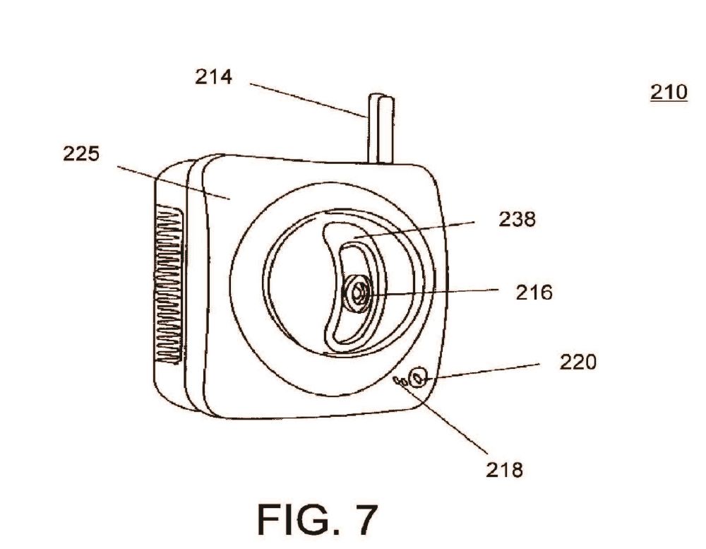
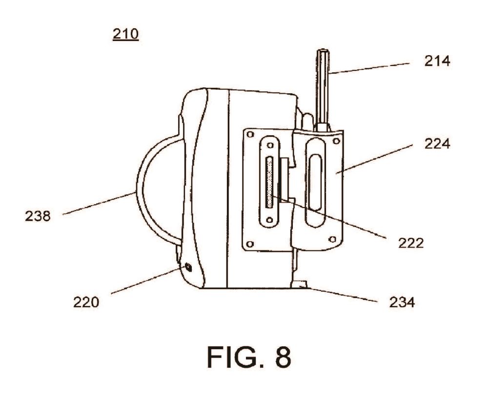
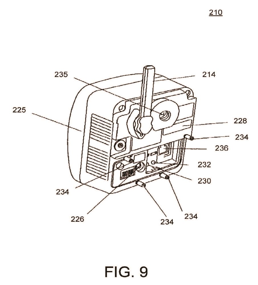
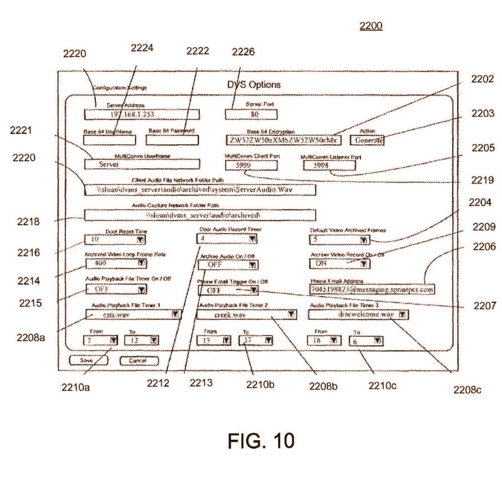
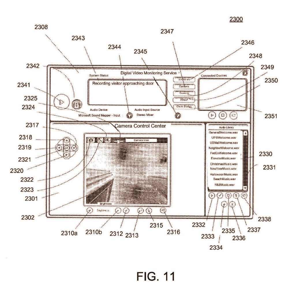
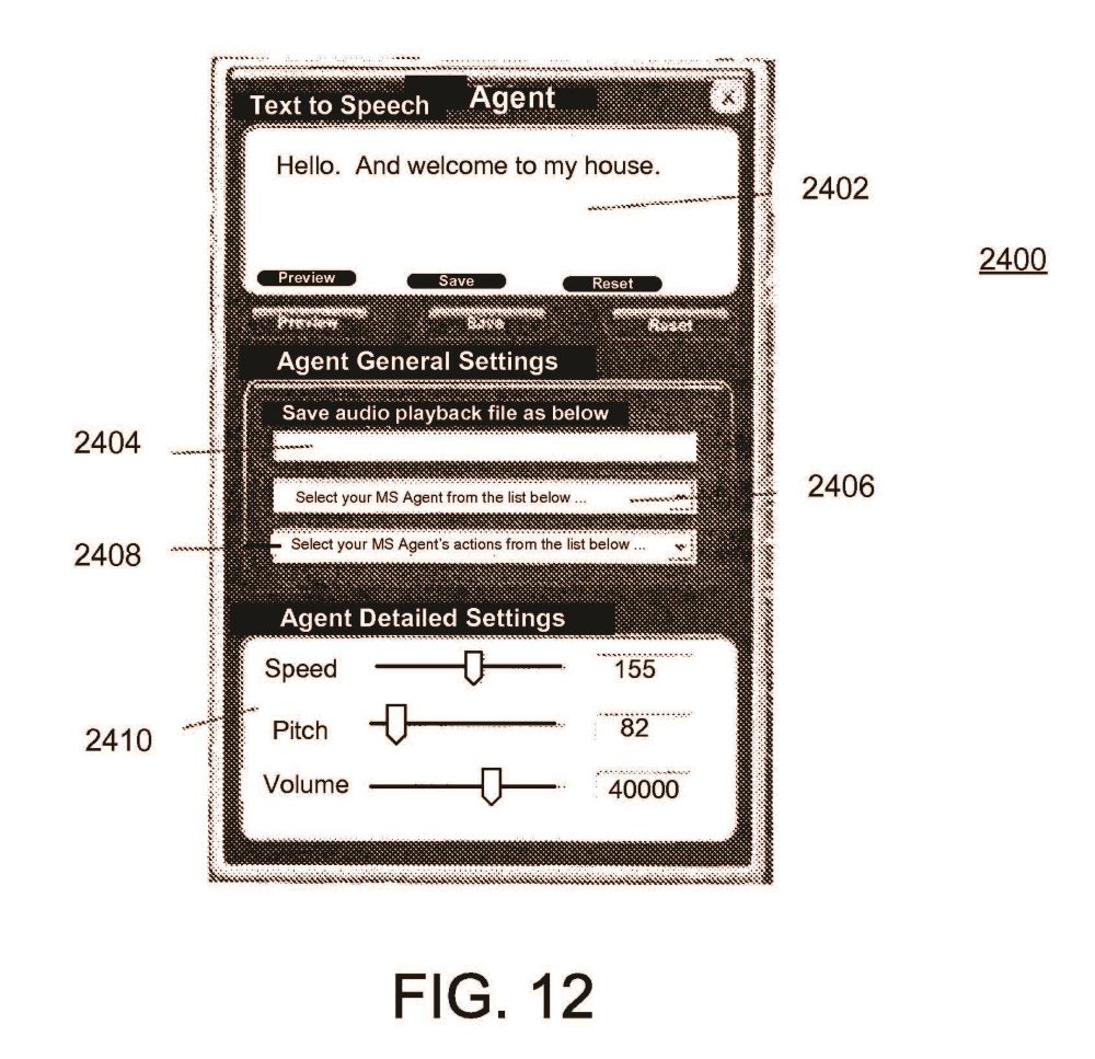


ABSTRACT
An audio-video communication system comprises a wireless exterior module located proximate an entrance, a computerized controller running a software application, and a remote peripheral device. The wireless exterior module includes a proximity sensor for detecting a person at the entrance, a video camera for recording an image of the person at the entrance, a microphone for recording the person at the entrance, a speaker for playing audio to the person at the entrance, a transmitter for communicating sounds and images of the person at the entrance, and a receiver for receiving communications at the wireless exterior module. The computerized controller is disposed in wireless electronic communication with the wireless exterior module via the transmitter and the receiver of the wireless exterior module. The remote peripheral device is configured to electronically communicate with the computerized controller for viewing an image from the video camera communicated from the wireless exterior module.
DESCRIPTION
I. CROSS REFERENCE TO RELATED APPLICATION
This application is a continuation patent application of, and claims the benefit under 35 U.S.C. §120 to, U.S. patent application Ser. No. 11/618,615, filed Dec. 29, 2006, published as U.S. Patent Appl. Publication No. 2007/0103548 A1, which patent application is a continuation-in-part patent application of, and claims the benefit under 35 U.S.C. §120 to, U.S. patent application Ser. No. 10/682,185, filed Oct. 9, 2003, published as U.S. Patent Application Publication No. 2005/0285934 A1, and now granted as U.S. Pat. No. 7,193,644, which patent application is a nonprovisional patent application of U.S. patent application Ser. No. 60/418,384, filed on Oct. 15, 2002, expired. Each of these patent applications, patent application publications, and patent is hereby incorporated herein by reference.
II. BACKGROUND OF THE INVENTION
There are numerous problems presently associated with receiving visitors at a home or office. When the resident of the home or occupant of the office (hereinafter generally referred to as either resident or occupant) is absent, there is often no message for the visitors, no means to leave an interactive message for the resident, and no means to ensure that unwanted access is not obtained. Moreover, answering the call of someone at a door of a dwelling can present certain security risks to an occupant therein. This situation can be especially inconvenient when, for example, a delivery or repair person arrives and the resident is not present. When the resident is present, on the other hand, there are also problems associated with receiving visitors. Some visitors may be unwelcome, for example, and it is often not evident that a visitor is a threat or an annoyance until after the door is open.
There are many types of systems for receiving a person by an occupant or resident and/or on the behalf of the occupant or resident. Such systems include those disclosed in each of: U.S. Pat. No. 5,148,468 titled “Door Answering System”, which issued Sep. 15, 1992 to Marrick et al; U.S. Pat. No. 5,303,300 titled “Security Door Phone Device,” which issued Apr. 12, 1994 to Eckstein; U.S. Pat. No. 5,406,618 titled “Voice Activated, Hands Free Telephone Answering Device,” which issued Apr. 11, 1995 to Knuth, et al.; and U.S. Pat. No. 5,657,380 titled “Interactive Door Answering and Messaging Device with Speech Synthesis,” which issued to Mozer on Aug. 12, 1997. Nevertheless, a need remains for further improvement in such a system.
III. SUMMARY OF THE INVENTION
The invention includes many aspects and features. Moreover, while many aspects and features of the invention relate to, and are described in, the context of a system for receiving a person at an entrance, such as, an entrance to a home or business, the invention is not limited to use only in such context and may be used and has applicability in other contexts as well.
In one aspect of the invention, an audio-video communication system comprises a wireless exterior module located proximate an entrance, a computerized controller running a software application and a remote peripheral device. The wireless exterior module includes a proximity sensor for detecting a person at the entrance, a video camera for recording an image of the person at the entrance, a microphone for recording sound of the person at the entrance, a speaker for playing audio to the person at the entrance, a transmitter for communicating sounds and images of the person at the entrance, and a receiver for receiving communications at the wireless exterior module. The computerized controller is disposed in wireless electronic communication with the wireless exterior module via the transmitter and the receiver of the wireless exterior module. The computerized controller is configured to control recording of communications with the wireless exterior module and playback of such recording, and the software application includes a graphic user interface that enables a user to view images from the video camera communicated from the wireless exterior module. The remote peripheral device is configured to electronically communicate with the computerized controller for viewing an image from the video camera communicated from the wireless exterior module.
In a feature of the first aspect, the audio-video communication system further comprises a second wireless exterior module located proximate an entrance, with the second wireless exterior module having a proximity sensor for detecting a person at the entrance, a video camera for recording an image of the person at the entrance, a microphone for recording sound of the person at the entrance, a speaker for playing audio to the person at the entrance, a transmitter for communicating sounds and images of the person at the entrance, and a receiver for receiving communications at the wireless exterior module. The computerized controller running the software application is further disposed in wireless electronic communication with the second wireless exterior module via the transmitter and the receiver of the second wireless exterior module.
In another feature of this aspect, the remote peripheral device is configured to remotely actuate the camera of the wireless exterior module. In an additional feature, the graphic user interface enables a user to view streaming video with the remote peripheral device. In yet another feature, the remote peripheral device comprises a cell phone. In still yet another feature, the remote peripheral device comprises a video phone. In further features, the remote peripheral device comprises a computer and a personal digital assistant.
In an additional feature, the entrance comprises an entrance of a business. In another additional feature, the entrance comprises an entrance of a residence. In a further feature, the wireless exterior module includes a display screen. In still a further feature, the wireless exterior module includes a keypad comprising a touch screen or a keyboard. In yet a further feature, the wireless exterior module is portable and includes a locking mechanism and an electrical receptacle for quickly attaching to a source of electricity.
In another feature, the wireless exterior module has a portable energy source and is secured in a holster. In yet another feature, the computerized controller comprises a personal computer. In still yet another feature, the computerized controller is disposed in electronic communication with a public switching telephone network (PSTN).
In a further feature, the computerized controller is disposed in electronic communication with the Internet. In an additional feature, the audio-video communication system further comprises an electronically actuated lock that is configured to be unlocked by the computerized controller. In another feature, the system further comprises a voice recognition system.
In still a further feature, a transceiver includes the transmitter for communicating sounds and images of the person at the entrance and the receiver for receiving communications at the wireless exterior module. In yet another feature, the computerized controller includes an image recognition module for identifying at least one of faces, eyes, and fingerprints.
In a second aspect of the invention, a method for two-way audio-video communications between a first person at an entrance and a second person comprises the steps of (a) detecting, with a proximity sensor located proximate an entrance, the presence of a first person at the entrance; and (b) providing real time audio-video communications between the first person at the entrance and a second person using a wireless handheld device. Step (b) is done by (i) transmitting, to the wireless handheld device of the second person, video of the first person at the entrance recorded using a camera located proximate the entrance, (ii) transmitting, to the wireless handheld device of the second person, audio of the first person at the entrance recorded using a microphone located proximate the entrance, and (iii) transmitting, to a speaker located proximate the entrance for playing to the first person at the entrance, audio of the second person recorded using the wireless handheld device.
In a feature of this aspect, the transmitting includes wireless communications between both the camera and microphone located proximate the entrance and a computerized controller running a software application including a graphic user interface by which the audio-video communications between the first person and the second person are established. In another feature, the method further comprises the step of playing a recorded greeting to the first person at the entrance upon the detection of the first person at the entrance with the proximity sensor. With regard to this feature, the method further comprises determining, by a user with a remote peripheral device, the recorded greeting that is played through a graphical user interface. With further regard to this feature, the recorded greeting is selected by the user from a plurality of recorded greetings. It accordance with this feature, the recorded greetings are seasonal greetings. It is preferred that the recorded greeting includes audio and video.
In an additional feature, the method further comprises the step of posting, by the user from a remote peripheral device, a video greeting for presentation to a first person at the entrance. In further features, the wireless handheld device comprises a cell phone, a video phone, and a personal digital assistant.
In yet another feature, the entrance comprises an entrance of a business. In still a further feature, the entrance comprises an entrance of a residence. In another feature, the method further comprises the step of saving a recording of the two-way audio-communications in a database for later playback. In yet another feature, the method further comprises transmitting, to a video display located proximate the entrance for presentation to the first person at the entrance, video of the second person recorded using the wireless handheld device.
In an additional feature, the transmitting includes communications over the Internet. In further features, the transmitting includes communications over a cellular network and over a satellite network. In yet another feature, the method further comprises remotely actuating the camera located proximate the entrance using the wireless handheld device. In still further features, the step of remotely actuating the camera includes zooming an image of the first person at the entrance and remotely moving the camera to change the view of the camera.
In a third aspect of the invention, a method for receiving a person at an entrance comprises the steps of (a) detecting, with a proximity sensor located proximate an entrance, the presence of a person at the entrance; (b) transmitting, to a computerized controller running a software application, video of the person at the entrance recorded using a camera located proximate the entrance; and (c) providing, with the application software running at the computerized controller, a graphic user interface to a remote peripheral device by which a user of the remote peripheral device may view the video of the person at the entrance.
In a feature of this aspect, the method further comprises the step of saving, in accordance with the application software running at the computerized controller, the video of the person at the entrance in a database in association with a timestamp. In other features, the video is viewed using the remote peripheral device in real-time, viewed using the remote peripheral device after the person at the entrance has left, and is streamed to the remote peripheral device.
In an additional feature, the method further comprises the step of transmitting, to the computerized controller running the software application, audio of the person at the entrance recorded using a microphone located proximate the entrance; wherein the graphic user interface provided to the remote peripheral device further enables a user of the remote peripheral device to hear the audio of the person at the entrance. In another feature, the method further comprises the step of playing a recorded greeting to the person at the entrance upon the detection of the person at the entrance with the proximity sensor.
In another feature, the method further comprises determining, by a user with the remote peripheral device, the recorded greeting that is played through a graphical user interface. With regard to this feature, the recorded greeting may be selected by the user from a plurality of recorded greetings, the recorded greetings may be seasonal greetings, and the recorded greeting may include audio and video.
In yet another feature, the method further comprises the step of posting, by the user from the remote peripheral device, a video greeting for presentation to a person at the entrance. In other features, the remote peripheral device comprises a cell phone, a video phone, a computer, and a personal digital assistant. In still other features, the entrance comprises an entrance of a business and an entrance of a residence.
In still another feature, the method further comprises remotely actuating the camera located proximate the entrance using the remote peripheral device. In further features, the step of remotely actuating the camera includes zooming an image of the person at the entrance and remotely moving the camera to change the view of the camera.
In addition to the aforementioned aspects and features of the present invention, it should be noted that the present invention further encompasses the various possible combinations of such aspects and features.
IV. BRIEF DESCRIPTION OF THE DRAWINGS
One or more preferred embodiments of the invention now will be described in detail with reference to the accompanying drawings.
FIG. 1 is a schematic diagram of a system in accordance with a preferred embodiment of the invention.
FIG. 2 is a planar view of the font of a DVMS module of the system of FIG. 1
FIG. 3 is a planar view of the front of a DVMS transceiver of the system of FIG. 1.
FIG. 4 is a block diagram overview of a method in accordance with a preferred embodiment of the invention.
FIG. 5 a block diagram extension of the method of FIG. 4.
FIG. 6 is a schematic diagram of a system in accordance with another preferred embodiment of the invention.
FIG. 7 is a perspective view of the front of a wireless network camera of the system of FIG. 6.
FIG. 8 is a side view of the wireless network camera of FIG. 7.
FIG. 9 is a perspective view of the rear of the wireless network camera of FIG. 7.
FIG. 10 is a representative screen view of a wireless command center of the system of FIG. 6, wherein various parameter settings for configuring, e.g., the audio, video, server, and cell phone options are illustrated.
FIG. 11 is a screen view of the normal operating mode interface of the wireless command center of FIG. 10, wherein a user is able to dynamically control a wireless network camera, view video images generated by the wireless network camera, listen and send both pre-canned and live audio files, and review archived system events.
FIG. 12 is a dialog box screen view of the text-to-voice synthesizer module of the wireless command center of FIG. 10.
FIG. 13 is a dialog box screen view of the recorded voice synthesizer module of the wireless command center of FIG. 10.
FIG. 14 is a planar view of the front of a wireless pocket PC that is connected to a wireless network, wherein a user of the wireless pocket PC is able to dynamically control the wireless network camera, view video images generated by the wireless network camera, listen and send both pre-canned and live audio files, and review archived system events in the system of FIG. 6.
V. DETAILED DESCRIPTION
As a preliminary matter, it will readily be understood by one having ordinary skill in the relevant art (“Ordinary Artisan”) that the present invention has broad utility and application. Furthermore, any embodiment discussed and identified as being “preferred” is considered to be part of a best mode contemplated for carrying out the present invention. Other embodiments also may be discussed for additional illustrative purposes in providing a full and enabling disclosure of the present invention. Moreover, many embodiments, such as adaptations, variations, modifications, and equivalent arrangements, will be implicitly disclosed by the embodiments described herein and fall within the scope of the present invention.
Accordingly, while the present invention is described herein in detail in relation to one or more embodiments, it is to be understood that this disclosure is illustrative and exemplary of the present invention, and is made merely for the purposes of providing a full and enabling disclosure of the present invention. The detailed disclosure herein of one or more embodiments is not intended, nor is to be construed, to limit the scope of patent protection afforded the present invention, which scope is to be defined by the claims and the equivalents thereof. It is not intended that the scope of patent protection afforded the present invention be defined by reading into any claim a limitation found herein that does not explicitly appear in the claim itself.
Thus, for example, any sequence(s) and/or temporal order of steps of various processes or methods that are described herein are illustrative and not restrictive. Accordingly, it should be understood that, although steps of various processes or methods may be shown and described as being in a sequence or temporal order, the steps of any such processes or methods are not limited to being carried out in any particular sequence or order, absent an indication otherwise. Indeed, the steps in such processes or methods generally may be carried out in various different sequences and orders while still falling within the scope of the present invention. Accordingly, it is intended that the scope of patent protection afforded the present invention is to be defined by the appended claims rather than the description set forth herein.
Additionally, it is important to note that each term used herein refers to that which the Ordinary Artisan would understand such term to mean based on the contextual use of such term herein. To the extent that the meaning of a term used herein-as understood by the Ordinary Artisan based on the contextual use of such term-differs in any way from any particular dictionary definition of such term, it is intended that the meaning of the term as understood by the Ordinary Artisan should prevail.
Furthermore, it is important to note that, as used herein, “a” and “an” each generally denotes “at least one,” but does not exclude a plurality unless the contextual use dictates otherwise. Thus, reference to “a picnic basket having an apple” describes “a picnic basket having at least one apple” as well as “a picnic basket having apples.” In contrast, reference to “a picnic basket having a single apple” describes “a picnic basket having only one apple.”
When used herein to join a list of items, “or” denotes “at least one of the items,” but does not exclude a plurality of items of the list. Thus, reference to “a picnic basket having cheese or crackers” describes “a picnic basket having cheese without crackers”, “a picnic basket having crackers without cheese”, and “a picnic basket having both cheese and crackers.” Finally, when used herein to join a list of items, “and” denotes “all of the items of the list.” Thus, reference to “a picnic basket having cheese and crackers” describes “a picnic basket having cheese, wherein the picnic basket further has crackers,” as well as describes “a picnic basket having crackers, wherein the picnic basket further has cheese.”
Referring now to the drawings, one or more preferred embodiments of the present invention are next described. The following description of one or more preferred embodiments is merely exemplary in nature and is in no way intended to limit the invention, its applications, or uses.
The System of FIG. 1
FIG. 1 is a schematic diagram of a system 100 in accordance with a preferred embodiment of the invention. For purposes of providing an enabling description, the system 100 is described in the context of a door answering system for receiving a person at a home or office and is capable of controlling access to the home or office. In FIG. 1, the exterior of the home or office is differentiated from the interior by demarcation line 115, which represents a wall or other similar structure. The wall 115 includes an entrance in the form of a door 114 and an electronically actuated lock 116 for selectively locking and unlocking the door 114.
A computerized controller in the form of a personal computer 80 is disposed in the interior and is configured to selectively actuate the lock 116. The personal computer 80 preferably includes a DVD-R/W 84, a CD-ROM R/W 92, and a hard drive 86. One or more of these components 84,92,86 of the personal computer 80 preferably are utilized for recording video and audio communications that are transmitted to and from the DVMS module 10 (described in further detail below) and for playing video and audio communications that are stored via the personal computer 80.
The personal computer 80 also may include a voice generator 90 for use in generating prompts, which either exists as pre-recorded messages or are generated by a voice synthesizer. Each of these components 84,92,86,90 of the personal computer 80 may be separately disposed from the personal computer and connected, for example, by a switch 88, or may form part of the personal computer 80 and be disposed in electronic communication with a bus of the personal computer 80 within the housing thereof.
A speaker 44 is disposed in electronic communication with the personal computer 80. The speaker 44 is not shown as being wireless, but could be. Moreover, one speaker 44 is shown, but additional speakers could be used in the system 100. Furthermore, speaker 44 in FIG. 1 is represented as being separate from the personal computer 80, however, the speaker 44 could alternatively form part of the personal computer 80.
The personal computer 80 preferably is disposed in electronic communication with the Internet. The connection with the Internet preferably is accomplished by a broadband connection such as a connection 81 provided by a satellite modem, a DSL model, or a cable modem, or any combination thereof.
The personal computer 80 also preferably is connected to a public switching telephone network (PSTN) 70, which enables communication by and with the personal computer 80 via standard telephone lines.
The personal computer 80 preferably has a battery backup as well as a means for detecting a loss in electrical power such that, when electrical power is lost the battery backup will provide sufficient operating time for the personal computer 80 to notify someone responsible for the maintenance of the system that there has been a loss of electricity. Notification of the loss of electricity can be important, since the loss of electrical power can be an indication of a burglary. Additionally, if there is no electricity, then appliances, such as refrigerators, air conditioners, and heaters, cannot function and significant damage can results if the electrical failure goes undetected for a substantial period of time.
The personal computer 80 runs a software application that includes a DVMS Database Application 82 and graphic user interfaces (GUIs). The personal computer 80, in accordance with the software application, controls communication in the system 100, coordinates multiple communication devices in the system 100, and is used to define responses to prompts and events in the system 100. The DVMS Database Application 82 and its uses are described in greater detail below.
The system 100 further includes a wireless router 42 located in the interior. The wireless router 42 in FIG. 1 is represented as being separate from the personal computer 80, however, the wireless router 42 could alternatively form part of the personal computer 80. The wireless router 42 is used to establish a wireless network and is disposed in electronic communication with the personal computer 80.
The system 100 also includes a DVMS module 10 located on the exterior of the home or office proximate the door 114. The DVMS module 10 is configured for use in the exterior of the home or office, which may include outdoor use in external residential or commercial locations. The DVMS module 10 is disposed in wireless communication with the wireless network, including the personal computer 80, via the wireless router 42.
With reference to FIG. 2, the DVMS module 10 preferably includes: a video camera 22; speakers 12; a proximity sensor 26; a microphone 20; an LCD display 16; a quick connect electrical receptacle 24; and a radiofrequency receiver/transmitter represented by antenna 18. The proximity sensor 26 activates the camera 22 upon detection of movement, which in turn relays an image or streaming video to the personal computer 80 where it is saved by the personal computer 80 in a database in association with a timestamp. Operation of the system is described in further detail below.
The DVMS module 10 optionally includes a small portable energy source, such as a battery that is rechargeable via the quick connect electrical receptacle 24, for portable use as well as for use in the event of a power failure.
The LCD display 16 screen preferably is a low energy screen reducing energy consumption. The LCD display 16 preferably comprises a touch screen and can be used to send and receive text similar to a keypad. Alternatively, or in addition thereto, the DVMS module 10 includes a keypad 14. In either case, the DVMS module 10 enables text messaging by a person at the exterior, which in turn enables a private non-audible conversation to be had and eliminates risks of eavesdropping by a passerby.
The DVMS module 10 also includes a locking mechanism 28 for receipt in a mounting holster (not shown). The locking mechanism 28 enables the DVMS module 10 to be installed securely wherever holstered, or to be moved to some other remote location, as desired. The DVMS module 10 thus is portable, much like a cell phone, and can be securely mounted and quickly connected to an electrical source.
It is anticipated that there could be multiple entrances to the home or office and, similarly, multiple DVMS modules similar to DVMS module 10 of FIG. 2 could be utilized, each disposed in wireless communication with the wireless network via the wireless router 42.
The system optional includes one or more DVMS transceivers 60. The DVMS transceivers 60 is configured for use in the interior of the home or office. As illustrated in FIG. 1, a DVMS transceivers 60 may be disposed in wireless communication with the wireless network, including the personal computer 80, and the DVMS module 10, via the wireless router 42. Additionally or alternatively, a DVMS transceivers 60 may be configured to wirelessly communicate directly with the DVMS module 10, thus bypassing communications through the wireless router 42.
With reference to FIG. 3, each DVMS transceiver 60 is portable and, like the DVMS module 10, the DVMS transceiver 60 communicates by short-range radiofrequency transmissions. The DVMS transceiver 60 includes: speakers 62; a microphone 63; an LCD display 66; a quick connect electrical receptacle 65; and a radiofrequency receiver/transmitter represented by antenna 68. The DVMS transceiver 60 optionally includes a small portable energy source, such as a battery that is rechargeable via the quick connect electrical receptacle 65, for portable use as well as for use in the event of a power failure. The DVMS transceiver 60 further includes a mute switch 61, which cuts-off the microphone 63, thus assuring a user of the DVMS transceiver 60 that a visitor can be monitored using the DVMS transceiver 60 without inadvertently sending an audible signal from the user.
The LCD display 66 screen preferably is a low energy screen reducing energy consumption. The LCD display 66 preferably comprises a touch screen and can be used is used to send and receive text similar to a keypad. Alternatively, or in addition thereto, the DVMS transceiver 60 includes a keypad 64. In either case, the DVMS module 60 enables text messaging by a user of the DVMS transceiver 60 with a person at the exterior using the DVMS module 10, which in turn enables a private non-audible conversation to be had and eliminates risks of eavesdropping by a passerby.
The system 100 further includes one or more remote peripheral devices. Such devices generally include video phones 72; in-car communication systems such as the well known ONSTAR system 74 currently found in GM cars; telephones 76; cell phones 77; personal computers 78; smartphones/personal digital assistants (PDAs) 79; and other similar communication devices. Each remote peripheral device is configured for electronic communication with the personal computer 80 via at least the PSTN connection 70 or the broadband connection 81.
As mentioned above, the personal computer 80 runs a software application that includes a DVMS Database Application 82 and graphic user interfaces (GUIs). The software application is configured and maintained by an administrator, who defines users thereof. The users in the system 100 are referred to as “occupants” reflecting their relation to the home or office.
Preferably, the occupants have various levels of access to the software application, depending on the privileges set by the administrator. The administrator may also set a level of security under which the system is to operate, particularly with respect to connections made using remote peripheral devices.
Other examples of configuration settings of the software application that are determined by the administrator include: aliases for a declared occupant such as, e.g., “Daddy” or “Momma”; passwords to access the software application; access codes to actuate the electronic lock controlled by the computerized controller; a number or other identifier that corresponds to an occupant's name; and at least one telephone number by which an occupant can be reached. The administrator also preferably defines a preferred hierarchy of storage of audio and video data, the location and number of backup devices, and whether replications of the database are to be kept.
Additionally, when setting up the software application, the administrator chooses, inter alia: a prompt for greeting a visitor; chooses an announcement that is to be given over a speaker within the interior when a visitor arrives; a prompt for requesting information from a visitor; a request instructing a visitor as to their choices in leaving a message or contacting a declared user; and the action that is to be performed by the computerized controller based on the input by the visitor.
The administrator also tailors the security/premise monitoring response by, inter alia: designating telephone numbers that the computerized controller calls when, for example, there is a loss of power; and designating telephone emergency numbers (e.g., telephone numbers for the police, the fire department, relatives, private security companies) that the computerized controller calls when an emergency is detected. The computerized controller also conducts self checks to confirm that all the components of the system are operational and keeps a log of the self checks, and the computerized controller preferably calls one or more designated numbers when a self check indicates a failure or otherwise improper operation.
The software application also can be configured to play background music or videos at different times of the year and/or different times of the day to reflect seasonal holidays, birthdays, and events. For instance, on Halloween the administrator may wish to have scary music and howls issuing from the DVMS module for receiving a person at that time. Furthermore, utilizing the computerized controller, the administrator can choose to use default prompts for interacting with a visitor or create customized prompts.
As hardware is added, such as the number of the DVMS modules and DVMS transceivers, the administrator can update both the network to include the additional devices and the computerized controller to accommodate the additional devices.
The software application also is configured to send voice, text, and video messages via email. The administrator can further set up redundant subsystems of the system 100.
The system 100, in use, enables secure and effective monitoring and interacting with a visitor at a residence or business, including, inter alia: the detection of the presence of a visitor at the exterior of the home or office via the proximity sensor 26, the interactive communication with the visitor, whether an occupant is present or absent from the home or office, the enablement of automated entry into the home or office by the visitor, and personalization of the process of receiving a visitor.
An exemplary method of use in the system 100 includes greeting and communicating with visitors of a business or residence. In accordance with the method, the presence of a visitor is detected via the proximity sensor 26 of the DVMS module 10, where the DVMS module 10 is mounted at or near an entrance to the business or residence. Upon the detection of the visitor by the proximity sensor 26, a message is communicated to the personal computer 80 from the DVMS module 10 indicating the detection of a visitor at the entrance. A recording is actuated by the personal computer 80, and the recording is stored in a computer-readable medium such as a database along with a beginning time-stamp. The arrival of a visitor is broadcast over a speaker within the home or office, such as speaker 44. An occupant can view the visitor on a display on the DVMS transceiver 60 or on a display of the personal computer 80, and the occupant can initiate a conversation at any time. The DVMS module 10 issues a greeting to the visitor and instructs the visitor to select a number from the keypad 14 of the DVMS module 10 in order to designate the occupant being visited. The entered number is communicated from the DVMS module 10 to the personal computer 80, where the software application confirms that the number corresponds to an occupant “y” who is “officially” present. An error message is generated if no individual corresponds to the number entered by the visitor. If no individual corresponds to the number entered by the visitor, then the visitor is prompted to select and press another number on the keypad 14 again designating the occupant being visited. The method then lists the choices again.
While this is going on, the door may be answered at any time, thereby resetting the software application to look for another visitor. The software application keeps track of the number of times a wrong number is entered and can generate a variety of responses to pranks, including calling the police, issuing warnings and/or a loud noise, or just thanking the visitor and asking him to return another time.
If appropriate, when the number designated by the visitor matches an occupant who is officially on the home or office, the speaker broadcasts that the visitor is here to see occupant “y”. Occupant “y” can signal the personal computer 80 to take a message, or occupant “y” may choose to use the DVMS transceiver 60 to speak directly with the visitor, or occupant “y” can answer the door.
If appropriate, the DVMS module 10 issues a prompt stating that occupant “y” is not available and asks the visitor if they wish to speak to occupant “y” or to leave a message.
If appropriate, at any time the software application can initiate a call to occupant “y” via a remote peripheral device for communication between occupant “y” and the visitor, and the software application can record both sides of the conversation between occupant “y” and the visitor. The occupant can view the visitor or initiate a conversation, as the occupant desires. A visitor never knows where the occupant is, unless the occupant tells the visitor of the occupant's location. A visitor also never knows if the occupant can be contacted, or if the occupant has just instructed the application to take a message. Using the method the conversation or messages can be relayed to the selected occupant without the visitor ever knowing where the location of the occupant. Only the occupant can disclose such location to the visitor as desired.
If the visitor elects to leave a message, then the method prompts the visitor to begin his message and then, optionally, offers him a chance to review and approve his message. The message or call is stored in computer readable medium, such as database, by the personal computer 80 in association with a beginning timestamp and an ending timestamp along with the occupant's mailbox number. At the end of the call or message, the software application can issue a closing statement and return to background music, if programmed to do so.
When the visitor departs, and is out of the range of the proximity sensor 26, all recording is stopped and saved in the database record, along with an ending timestamp. The occupant “y” can selectively sort to view the entire recorded visit, or just the message.
If the proximity sensor 26 indicates that there is another visitor, the method cycles back to the greeting step.
If the system has an electronically actuated lock, then the method also may include the steps of checking the number entered by the visitor to determine if it is a valid access code. The electronically actuated lock may be unlocked by entering an access code either at the DVMS module 10 or remotely therefrom. If the number is valid, then the lock is actuated, and if the number is not valid, then a prompt is made requested that the code be re-entered. Optionally, the prompt may further request a number be entered that corresponds to one of the occupants if assistance is needed and, if an occupant is selected, then calling the selected occupant. The method also may include tracking how many times the wrong code is entered; checking if the maximum allowed number of wrong entries have been made; and, when the maximum number of wrong entries is reached, either automatically calling a designated party and/or removing access privileges.
An occupant preferably has the option of remotely entering the access code, thereby actuating the electronically actuated lock, or instructing the GUI database application to go to a new high security level, wherein the lock cannot be accessed and notifying the visitor that the access code is not operational.
In the method, upon the entering of a valid access code assigned to a declared occupant, the software application optionally notifies the administrator or his designated representative that the declared occupant has now entered the home or office. The administrator would know who the individual should be. The administrator thus can confirm, by remotely viewing the recorded video, that the actual person who entered the access code is the declared occupant, and/or make a follow-up telephone call to the home or office. The system 100 also provides the options of allowing the visitor to converse with the occupant, leaving a message, or calling a remote peripheral device for communication with the occupant when he is either not present or is unavailable. The entrance is recorded and time stamped for sorting or viewing either in real time or at a later date.
The system 100 further enables the administrator or a declared occupant to, at any time, to turn on a camera and view images, access the recorded the video images, or post a video image from a remote peripheral device to computerized controller including associated components.
The system 100 preferably is inherently extensible in both form and function and is designed so that the system can be expanded to include multiple peripheral devices, both in direct and indirect communication with the computerized controller. Due to the use of the computerized controller and its interconnectivity, the disclosed system 100 can be configured to accommodate communications having a range of complexity.
As will be apparent from the foregoing, the system 100 provides an audio-video communication and answering system that provides real time communication between an exterior of a business or residence and an interior of the business or residence as well as a location remotely located to the business or residence.
As will be apparent from the foregoing, the system 100 provides an audio-video communication and answering system that provides real time communication between two or more rooms at a home or office and a remote location.
As will be apparent from the foregoing, the system 100 provides an audio-video communication and answering system that provides the ability to leave messages at a centralized location from a local or remote location.
In addition to the foregoing description of a method, FIG. 4 shows a block diagram illustrating an example of the use of a system of the invention as a door answering and messaging system at a residence. Furthermore, FIG. 5 shows a block diagram illustrating an example of the use of a system of the invention as a door answering and messaging system at a residence, wherein the system includes an electronically actuated lock. In the example, an occupant is attempting to gain access to the home or office.
As will now be apparent, systems in accordance with the invention achieve one or more of the foregoing benefits and features yet remain intuitive and easy to use.
In addition to the foregoing, it further is anticipated that, in certain deployments of the invention, voice recognition would be useful, particularly when the system enables access to a home or office. Voice recognition adds another layer of security, and can be used to facilitate those individuals who are unable to press a keypad. Similarly, image recognition of faces, eyes and fingerprints can also be included in the system for authentication, security, and access. The software application thus alternatively utilizes voice recognition and/or image recognition.
Furthermore, while no camera is shown located within the home or office, any number of cameras could be utilized on the interior.
It will also be appreciated that a business may be a tenant located within a building shared by other businesses. A DVMS module for the business thus would be utilized on the exterior of the business, i.e., at the “front door” of the business, which would be located within the interior of the common building.
In variations of systems of the invention, it should further be noted that one or more devices having the functionality of DVMS modules could be utilized in the interior for securing entrance to a room or group of rooms.
The System of FIG. 6
FIG. 6 is a schematic diagram of a system 2100 in accordance with another preferred embodiment of the invention. The system 2100 includes: a local area network 2200; a wireless digital camera 210; and a computerized controller in the form of a personal computer 240 (identified as the “Wireless Command Computer” in FIG. 6). The lines indicate communications between member devices and components of the system 2100 and such communications may be wired, wireless, or a combination of both wired and wireless. For purposes of providing an enabling description, the system 2100 is described in the context of a door answering system for receiving a person at a home or office and is capable of controlling access to the home or office. In FIG. 6, the exterior of the home or office is differentiated from the interior by a wall 2112 or other similar structure. The wall 2112 includes an entrance in the form of a door 2116 and an electronically actuated lock 2114 for selectively locking and unlocking the door 2116.
The personal computer 240 is disposed in the interior and is configured to selectively actuate the lock 2114. The personal computer 240 includes one or more components utilized for recording video and audio communications and for playing video and audio communications. The personal computer 240 also may include a voice generator for use in generating prompts, which either exists as pre-recorded messages or is generated by a voice synthesizer. Each of these components of the personal computer 240 may be separately disposed from the personal computer and connected, for example, by a switch, or may form part of the personal computer 240 and be disposed in electronic communication with a bus of the personal computer 240 within the housing thereof. A speaker 248 is disposed in electronic communication with the personal computer 240. Moreover, one speaker 248 is shown, but additional speakers could be used in the system 2100. Furthermore, speaker 248 in FIG. 6 is represented as being separate from the personal computer 240, however, the speaker 248 could alternatively form part of the personal computer 240.
The personal computer 240 preferably is disposed in electronic communication with the Internet. The connection with the Internet preferably is provided by a broadband connection through, for example, a wireless router 250. Such broadband connection may be accomplished by a satellite modem, a DSL model, or a cable modem, or any combination thereof. The personal computer 240 also preferably is connected to a public switching telephone network (PSTN) 70, which enables communication by and with the personal computer 240 via standard telephone lines.
The personal computer 240 preferably has a battery backup as well as a means for detecting a loss in electrical power such that, when electrical power is lost the battery backup will provide sufficient operating time for the personal computer 240 to notify someone responsible for the maintenance of the system that there has been a loss of electricity. Notification of the loss of electricity can be important, since the loss of electrical power can be an indication of a burglary. Additionally, if there is no electricity, then appliances, such as refrigerators, air conditioners, and heaters, cannot function and significant damage can results if the electrical failure goes undetected for a substantial period of time.
With regard to the wireless router 250, it is represented as being separate from the personal computer 240, however, the wireless router 42 could alternatively form part of the personal computer 240. The wireless router 42 is used, inter alia, to establish a wireless network and is disposed in electronic communication with the personal computer 240. The router 250 is WiFi compliant, and operates using a standardized protocol such as, for example, 802.11(b) and/or 802.11(g).
The wireless router 250 facilitates two-way communication over the local area network 2200 among the member devices and components of the wireless network 2200. Furthermore, the wireless router 250 preferably is disposed in electronic communication with the Internet and facilitates two-way communication between the member devices and components of the wireless network 2200 and remote devices communicating over the Internet. Such remote devices generally include video phones 275; in-car communication systems, such as the well known ONSTAR system 274 currently found in GM cars; telephones 276; cell phones 277; personal computers 278; smartphones/personal digital assistants (PDAs) 279; and other similar communication devices. Each remote device preferably is configured for electronic communication with one or more of the member devices and components of the wireless network 2200 via at least the PSTN connection 270 or a broadband Internet connection. Additionally, a remote device may be configured to communicate with one or more of the member devices and components of the wireless network 2200 via direct wireless communications with the wireless router 250 when such remote device is within communications range of the wireless router 250. Such direct wireless communications with the wireless router 250 is illustrated with the cell phone 277 in FIG. 6.
The wireless command computer includes a digital video system application (“DVS App”) 242 and a monitoring application 244. The DVS App 242 provides a set of customizable operating parameters for the wireless digital camera 210. The set of digital video operating parameters may include parameters selected from the group of: a default camera position; a number of frames per second; sensitivity and threshold of a motion sensor; length of a session; frequency of motion detection; and sensitivity and threshold of the motion detector. These parameters are conveyed to the camera operation application, discussed in further detail below. The monitoring application 244 includes a camera control screen that displays the camera webpage; and an operating screen that displays a set of operating parameters. The set of operating parameters may include parameters selected from the group of: a card file for cross-referencing MAC ID'S with cameras and pocket PCs on the wireless network; paths for logging and archiving files received from the camera; camera webpage addresses; email addresses for users; telephone numbers for cell phones; a designated greeting when a motion sensor is triggered; and security parameters. The monitoring application 244 further includes an audio library screen that displays the contents of a library of pre-recorded audio files. Typically, at least one pre-recorded audio file is a greeting audio file. In the context of the system 2100, the audio file can be sent over the local area network 2200, and can include, for instance, sounds, music, voice recordings, synthesized noises, and the like. The means of generating an audio file can be a microphone that feeds to an AID converter, which creates a digital audio file, such as a wav file or MP3 file, or a voice synthesized digital audio file. The monitoring application 244 generally includes a means of generating an audio file, and a command computer website that provides a command webpage with graphic controls for reviewing archived files. The monitoring application can further include a set of monitoring parameters that define the criteria for keeping or deleting a video file in memory, wherein the criteria includes available memory on system, age of file, and priority. The monitoring application also can further include an option to designate that the digital camera transmit video and audio data to more than one member device of the wireless network, and/or to split up audio and video data to two or more member devices. This feature is desirable if, for instance, it is preferred that either audio or video not be sent, or if a network member device—for instance a cell phone—is not configured to process both audio and video data. The monitoring application 244 also can include settings for notifying one or more designated individuals or a security service if an alarm is activated or if a predetermined condition is otherwise detected by a sensor. Such sensors may include, for example, smoke detectors, carbon monoxide detectors, laser beam detectors, broken window detectors, temperature detectors, radiation detectors, radon detectors, open window, door detectors, or a combination thereof. Moreover, such sensors may communicate via the local area network 2200.
The system 2100 includes a wireless digital camera 210 located on the exterior of the home or office proximate the door 2116. The wireless digital camera 210 includes a website application 246 and a camera operation application 247. The wireless digital camera 210 is shown in further detail in FIGS. 7-9. The wireless digital camera 210 preferably creates a series of images that are stored as a series of jpeg files which are displayed on a webpage of a website application 246 that is unique to a given camera 210. The camera 210 also includes a microphone 218, and the sound recorded by the microphone is digitized as an audio file, such as a .wav file or an MP3 file, that is transmitted along with the video as an audio file. This camera 210 preferably has a splash resistant body 225, a lens cover 238 over lens 216, and a wireless transceiver for audio 2-way audio communication. Furthermore, this camera 210 can pan, tilt, or move to a pre-set position. The camera 210 includes a motion sensor that triggers video recording with surveillance image quality, refreshing its image 30 frames per second, and includes a charge coupled device sensor to compensate for low light conditions. Communications via the wireless camera 210 also preferably are encrypted. The splash resistant body 225 allows the camera 210 to be used indoors or outdoors. The camera 210 also supports IPv6 (Internet Protocol Version 6). The audio feature of the camera 210 uses a Java applet that is installed during the installation. The camera 210 has a memory card 222 that is protected by a sealing door 224, a proximity detector or motion sensor 220, a microphone 218, a power input 226, an external microphone port 230, a LAN port 236, and a speaker port 232. The illustrated camera 210 has four mounting legs 234 and a mounting stand hole 235. The antenna 214 projects from the rear of the camera. A suitable wireless digital camera that has weather resistance is the camera currently sold in the United States by Panasonic under the part number BB-HCM371.
Every camera in the system 2100 preferably can be uniquely identified by a media access control (MAC) address that enables the personal computer 240, and each device in the system 2100 having a web browser, such as, e.g., a Windows Internet Explorer browser, or a Firefox browser, to be in wireless communication with camera 210 through the wireless router 250. While only one camera 210 is shown in FIG. 6, multiple cameras can be included in the system 2100, each with its own unique website accessible by multiple devices in the system 2100 having Internet browsers. In addition to displaying the video and audio on the camera's webpage, the website application 246 of the camera 210 displays graphic controls for actuating the camera 210, such as panning right and left, up and down, zoom in and zoom out, and adjustments for the amount of ambient light. These controls are illustrated in FIG. 11.
As previously stated, the camera 210 has a motion sensor 220 for detecting the presence of a person or a moving object with an adjustable level of sensitivity and a trigger threshold for initiating video recording, and, optionally issuing a verbal response, such as a greeting. The verbal response is an audio file, which can reside in the camera's memory as well as in the personal computer, in which case the verbal response can be transmitted, via the local area network 2200, to the camera 210. The camera 210 typically has a pre-set or default position, which can be static or dynamic. For instance, the camera 210 can be programmed to pan back and forth through a pre-set cycle or to zoom in and out, or any combination thereof. The motion sensor 220 has parameters for setting the sensitivity and a trigger threshold for initiating video recording. Upon initiation, the camera automatically starts recording video, which is displayed on the camera webpage in the form of video images, typically in serial form. The recording further can be transmitted to the personal computer 240 for saving for later viewing. In an alternative embodiment, the camera does not include a motion sensor 220 in the form of an additional piece of hardware but, instead, detects motion via a software application that analyzes the video images. In this alternative, the camera 210 records images on a routine basis and, when motion is detected, a video recording is initiated and a verbal response optionally is provided. Such software can be executed at the personal computer 210 or can be executed at the camera 210 and form part of the camera application 247.
The website application 246 of the digital camera 210 provides a webpage with graphic controls for operating the camera and a viewing area for viewing video images. When activate for recording the camera 210 provides digital video images that are displayed on the webpage. The camera 210 can be activated manually or self-activated by the motion sensor 220 that detects the presence of a person or a moving object. The motion sensor 220 has an adjustable level of sensitivity and a trigger threshold for initiating video recording. The camera 210 has a memory cache for saving a designated number or series of transmitted video images. Typically, when activated for video recording, the camera also activates audio recording, which provides audio files on the webpage generated by the digital camera's microphone 218. The camera 210 also includes means including the speaker 218 for playing received audio files.
Referring to FIG. 10, the screen 2200 for setting the parameters of the DVS application 242 is illustrated. Communications over the local area network 2200 between the camera 210 and command computer 240 are established using a MAC address of the camera 210 and/or an IP address 2224 for the camera. The default port 2226 for communications is 80. The camera 210 recognizes an encrypted username and password 2202. The DVS application 242 encrypts the username 2224 and the password 2222, using the generator 2203, resulting in the encrypted version 2202. The hierarchical structure of the member devices of the wireless network is defined in 2220, 2219 and 2205. The command computer 240 designated is named “Server”, as shown in the Username textbox 2221. The client port for uploading audio files 2219 is given as port 5999. An example of a client is a pocket PC 260 or cell phone 277 having a web browser. The listener port 2205 for down loading audio files is port 5998. The camera 210 has access to the audio files in a network-shared folder having a designated path 2220. When a greeting/verbal response is triggered by the motion sensor 220, the file is read from the shared folder 2220. Audio files received by the command computer 240 from the camera 210 are saved in the audio capture folder 2218. The received audio files can be accessed by the client, pocket PC 260, or cell phone 277, as well as the command computer 240. The door reset time 2216 is a parameter that designates the length of time in seconds that must pass after the motion sensor 220 no longer detects a visitor before a recording is stopped. The door audio record timer 2212 is the length of a visitor's message in seconds. The default video archived frames 2209 is the number of images or frames that are saved as an archived file. The archived video file 2216 can be played back at various speeds. The archived video loop frame rate 2216 is in frames per millisecond. Recall that the camera is capable of generating 30 frames, or 30,000 frames per millisecond. This feature 2216 allows the video to be slowed down. If the administrator wishes to cut off archiving audio files, the administrator can select this in box 2213. If the administrator wishes to cut off archiving video files, the administrator can select this in box 2209. The audio files can be turned off completely by using the audio playback parameter 2215. The DVS application 242 can be set to send a message to a cell phone or another computer. The phone email trigger 2207 sets this parameter, and the email address is entered into phone email address parameter 2207. The DVS enables different greetings/verbal responses to issue depending on pre-set criteria. The time of day is one criterion. As shown in FIG. 10, there are three audio files: “cats.wav” 2208 a, “creek.wavn 2208 b and “dracwelcome.wav” 2208 c, each of which will be triggered depending on the time of day. Pairs of boxes 2210 a are set from 7 to 12, text boxes 2210 b are set from 13 to 17, and text boxes 2210 c are set from 18 to 6. At 13 hours, or 1 PM, the greeting switches from “cats.wav” 2208 a to “creek.wavfl 2208 b, and at 6 PM the greeting switches from “creek.wav” 2208 b to “dracwelcome.wav” 2208 c. As will be discussed below, additional options also exist for playing the audio files.
As shown in FIG. 11, the camera's webpage is incorporated as a screen in the monitoring application 244 of the wireless command computer 240. In the screenshot of the monitoring application 2300 of FIG. 11, the lower main screen 2301 displays the camera webpage. The camera webpage is comprised of the streaming video images 2301, an icon 2322 for taking a snapshot, an icon 2323 enabling the user to talk via the camera using the command computer's microphone, an icon 2324 enabling the user to hear sound picked up by the camera's microphone 218, and icon 2325 enabling the user to zoom in and out. Additionally the webpage has graphic controls for remotely positioning the camera, adjusting brightness and automatic panning. The cross-shaped icon on the side has left arrow 2319 for turning the lens left, a right arrow 2317 for turning the lens right, an up arrow 2318 for turning the lens up, a down arrow 2320 for turning the lens down, and a center button 2321, which returns the camera to its default position. On the bottom of the webpage is an icon 2310 a for increasing the brightness when the light is low, and icon 2310 b for decreasing the brightness when the light is high. Icon 2312 sets the brightness to the default position, and icon 2316 is a reset button that returns all parameters to the factory settings. The camera automatically pans back and forth when button 2313 is clicked, and pans up and down when button 2315 is clicked. Panning is stopped by re-clicking the pan icons. The double curved arrow icon 2316 refreshes the camera controls. The audio library screen 2330 contains a list of all the currently recorded audio files. A scroll bar 2331 enables the user to quickly move down the list. To play a selection, a file is selected with the cursor, and then arrow icon 2332 is clicked. The check icon 2333 designates a file as a greeting/verbal response file. The square icon 2334 is the stop button, the plus icon 2335 initiates a module for adding a new audio file, the X icon 2336 deletes a selected audio file, the double arrow icon 2337 causes all checked audio files to be played in random order, and the icon 2338 is a reset button. The top screen 2308 contains a number of options, including starting and running the DVMS service. Large button 2341 turns the program off when clicked, and on when clicked again. Clicking on the lock icon 2342 actuates the door lock. Screen 2343 contains information about what is occurring at the camera, and other system performance information. Drop down icon 2344 opens a dialog box mapping all the sounds and multimedia properties. Drop list icon 2345 displays a list of input devices, such as the microphone on the command computer 240, when talking directly to the camera 210, which needs to be selected to conduct real time conversations. The connected devices screen 2351 displays a list of the wireless network deices, and whether they are currently available. The archives button 2346 activates a screen that lists all the archived video and audio files, and a timestamp for when they were created. The options button 2347 activates the DVS screen 2200 for configuring the application.
The camera has a software package that is run when initializing a new or an addition camera, where communication is established using the MAC address and the subsequent assignment of an IP address. Clicking the camera button 2348 starts that software. The about button 2349 has general information about the version of the DVMS system and contact information. The status button 2350 clears screen 2351.
When recording an audio file, the user can use a synthesizer module or voice recording module. The synthesizer module is a dialog box 2400 shown in FIG. 12, and the voice recording module is a dialog box 2500 shown in FIG. 13. The synthesizer module and the voice recording modules are Microsoft open source modules. In the voice synthesizer module, text is entered into screen 402 and then saved in path 404. An animated character/agent pops up on the command computer when the audio file is played, and characteristics of the agent are selected using screens 2406, 2408, 2410. For instance, a wizard can be selected as the MS Agent, and the wizard flies quickly, and speaks loudly with a low pitch. In FIG. 13, the user can record his or another's voice, or some sound, music, or other audible sound.
The local area network 2200 optionally includes one or more portable devices such as the pocket PC 260 represented in FIG. 6 and shown in detail in FIG. 14. The pocket PC 260 is configured with a client DVMS application. The pocket PC 260 is wireless, having antenna 262 that communicates with the personal computer 240 and the wireless digital camera 210 via wireless modem 250. Similar to the personal computer 240, the pocket PC 260 includes a display screen 2802 for viewing streaming video from the digital camera 210, an “Image” icon 2822 for saving a snapshot, a listen icon 2824 which plays audio from the camera, and a talk icon 2823 for transmitting audio to the camera. The audio volume is adjusted using thumb wheel 261. The pocket PC 260 further includes controls for pointing the camera in the desired direction including: menu selection 2819 for left, menu selection 2818 for up, menu selection 2817 for right, menu selection 2820 for down, and menu selection 2821 to return to the camera 210 the default position. The door lock is unlocked for access using menu selection 2808, which transmits an access code in the form of text to the locking mechanism 2114. The lower screen 2843 displays the status of member devices in the local area network 2200. The library of audio files is accessible through the set button 2830, and the play button 2833 selects the audio file to be played.
While not explicitly shown, it is anticipated that the system 2100 may include voice recognition and image recognition for additional security in authentication and access.
The system provides the options of allowing the visitor to converse with the occupant, leave a message, or call a remote peripheral device for communication with the occupant when he is either not present or unavailable. The visit is recorded and time stamped for sorting or viewing either in real time or at a later date. The system achieves these features, while still presenting a system that is intuitive and easy to use. The digital video monitoring system is extensible, scalable, and flexible in that the number of members of the wireless network can be readily expanded, the system provides and audio and video record of events, and a number of the components are currently off-the-shelf computerized devices that can be configured for the system. Finally, the system allows the users to achieve a high level of security and anonymity.
As will be apparent from the foregoing, the system 2100 enables wireless audio-video communication by all the member devices with each digital camera and the command computer; the system 2100 enables the option of having a visitor converse with an occupant, leave a message, or contact a remote device for communication with a member of the network that is offsite; the system 2100 enables a wireless digital camera to generate and audio and video recording of a visitor upon the sensing that a visitor is proximate the door, with the recording being viewed in real time, or at a later time, either locally or remotely; the system 2100 is highly extensible and can be easily adapted to control many cameras, the images of which can be simultaneously viewed by multiple individuals by merely browsing the individual camera's website that is unique to each camera. The system 2100 also is highly scalable due to the incorporation of a wireless network in the local area network 2200; the system 2100 enables an alarm and or automated calls to designated institutions and individuals when there is a security breach detected; the system 2100 allows users having the proper privileges to remotely permit entrance to a building; the system 2100 can be customized to reflect holidays, special occasions, and various levels of security.
Based on the foregoing description, it will be readily understood by those persons skilled in the art that the invention is susceptible of broad utility and application. Many embodiments and adaptations of the invention other than those specifically described herein, as well as many variations, modifications, and equivalent arrangements, will be apparent from or reasonably suggested by the present invention and the foregoing descriptions thereof, without departing from the substance or scope of the present invention. Accordingly, while the invention has been described herein in detail in relation to one or more preferred embodiments, it is to be understood that this disclosure is only illustrative and exemplary of the invention and is made merely for the purpose of providing a full and enabling disclosure of the invention. The foregoing disclosure is not intended to be construed to limit the present invention or otherwise exclude any such other embodiments, adaptations, variations, modifications or equivalent arrangements, the invention being limited only by the claims appended hereto and the equivalents thereof.
CLAIMS
1. A detection and viewing system, comprising:
(a) a wireless device associated with a door and configured to communicate video data, the wireless device including a camera for providing the video data;
(b) a sensor for activating the camera;
(c) a plurality of peripheral devices, each peripheral device associated with a respective user; and
(d) a computer configured for communication with the wireless device and configured for communication with each of the peripheral devices;
(e) wherein the computer executes software, in accordance with which,
(i) the association of each of the peripheral devices with a respective user is maintained,
(ii) video data from the wireless device is received by the computer upon actuation of the sensor, and
(iii) a graphical user interface is provided through which video data from the wireless device is accessible by each respective user using one of the peripheral devices.
2. The detection and viewing system according to claim 1, wherein the wireless device further includes a microphone, a speaker, an RF transmitter, and an RF receiver.
3. The detection and viewing system according to claim 2, wherein audio data is communicated with the video data.
4. The detection and viewing system of claim 1, wherein, in accordance with the software, video data received from the wireless device is recorded, and access to the recorded video data is provided through the graphical user interface.
5. The detection and viewing system according to claim 4, wherein the video data is recorded to a storage device selected from the group of a CD-ROM R/W, a DVD R/W, a camera card, a tape drive, and a hard drive.
6. The detection and viewing system according to claim 1, wherein, in accordance with the software, the computer associates one of various levels of access privileges to each user.
7. The detection and viewing system of claim 1, wherein, in accordance with the software, the computer contacts a particular one of the users by sending a communication to the respective peripheral device associated with that user upon the triggering of the sensor.
8. The detection and viewing system of claim 1, wherein, in accordance with the software, the computer facilitates audio communications between a person using the wireless device, and a particular one of the users, by initiating communications with the respective peripheral device associated with that user.
9. The detection and viewing system of claim 1, wherein the computer is configured for communication, via the Internet, with one or more of the plurality of peripheral devices such that audio and video data from the wireless device is remotely accessible via the Internet by a respective user using one of the peripheral devices.
10. The detection and viewing system of claim 1, wherein the computer is configured for communication, via a public switching telephone network, with one or more of the plurality of peripheral devices such that audio and video data from the wireless device is remotely accessible via the public switching telephone by a respective user using one of the peripheral devices.
11. The detection and viewing system of claim 1, wherein the computer is configured for communication, via a local area network, both with the wireless device and with one or more of the plurality of peripheral devices such that audio and video data from the wireless device is accessible via the local area network by a respective user using one of the peripheral devices.
12. The detection and viewing system of claim 1, wherein the plurality of peripheral devices each comprises a digital communication device.
13. The detection and viewing system of claim 11, wherein at least one of the plurality of peripheral devices comprises a cell phone, telephone, video-cell phone, computer, personal digital assistant, video-personal digital assistant, satellite telephone, or pager.
14. The detection and viewing system according to claim 1, wherein the wireless device and at least one of the peripheral devices are configured for communications via text messaging.
15. The detection and viewing system of claim 1, wherein the wireless device is portable, has a locking mechanism, and an electrical receptacle for quickly attaching to a source of electricity, and wherein the wireless device further includes a portable energy source.
16. The detection and viewing system according to claim 1, wherein the computer comprises a module for authenticating a user based on a biometric of the user.
17. The detection and viewing system according to claim 16, wherein the biometric comprises at least one of the group of a user's face, eye, voice, and fingerprint.
18. The detection and viewing system according to claim 1, wherein the computer comprises a voice-generation apparatus.
19. A detection and viewing system, comprising:
(a) a wireless device associated with a door and configured to communicate video data;
(b) a sensor associated with the door for activating of the camera upon triggering of the sensor;
(c) a plurality of peripheral devices, each peripheral device associated with a respective user; and
(d) a computer configured for communication with the wireless device and configured for communication, via the Internet, with each of the peripheral devices;
(e) wherein the computer executes software, in accordance with which,
(i) the association of each of the peripheral devices with a respective user is maintained,
(ii) video data from the wireless device is received and stored by the computer,
(iii) a graphical user interface is provided through which video data from the wireless device is accessible, via the Internet, by each respective user using one of the peripheral devices, and
(iv) each user is authenticated based on a biometric of the user.
20. A detection and viewing system, comprising:
(a) a wireless device associated with a door and configured to communicate audio and video data, the wireless device including a sensor, a camera, a microphone, a speaker, an RF transmitter, and an RF receiver, the wireless device communicating the audio and video data upon triggering of the sensor;
(b) a plurality of peripheral devices, each peripheral device associated with a respective user; and
(c) a computer configured for communication with the wireless device and configured for communication via the Internet with each of the peripheral devices;
(d) wherein the computer executes software, in accordance with which,
(i)the association of each of the peripheral devices with a respective user is maintained,
(ii) audio and video data from the wireless device is received by the computer,
(iii) a graphical user interface is provided through which audio and video data from the wireless device is accessible via the Internet by each respective user using one of the peripheral devices, and
(iv) audio and video data received from the wireless device is recorded, and access to the recorded audio and video data is provided through the graphical user interface.
CITATIONS
| Cited Patent | Filing date | Publication date | Applicant | Title |
|---|---|---|---|---|
| US4804945 | Oct 29, 1987 | Feb 14, 1989 | Millet; Terrance | Door alarm with infrared and capacitive sensors |
| US4931789 | May 12, 1988 | Jun 5, 1990 | Universal Photonix, Inc. | Apparatus and method for a universal electronic locking system |
| US5031228 | Sep 14, 1988 | Jul 9, 1991 | A. C. Nielsen Company | Image recognition system and method |
| US5148468 | Oct 24, 1990 | Sep 15, 1992 | Arnold; Gregory J. | Door answering system |
| US5303300 | Jun 29, 1992 | Apr 12, 1994 | Eckstein; Donald | Security door phone device |
| US5406618 | Oct 5, 1992 | Apr 11, 1995 | Phonemate, Inc. | Voice activated, handsfree telephone answering device |
| US5428388 | Jun 15, 1992 | Jun 27, 1995 | Richard von Bauer | Video doorbell system |
| US5657380 | Sep 27, 1995 | Aug 12, 1997 | Sensory Circuits, Inc. | Interactive door answering and messaging device with speech synthesis |
| US5896165 | Apr 9, 1997 | Apr 20, 1999 | Texas Instruments Incorporated | Method and system for a video answering machine |
| US5966432 | Apr 14, 1997 | Oct 12, 1999 | Nortel Networks Corporation | Remote answering of doorbell |
| US6041106 | Jan 15, 1997 | Mar 21, 2000 | Elite Entry Phone Corp. | Access control apparatus for use with buildings, gated properties and the like |
| US6049598 | Aug 28, 1997 | Apr 11, 2000 | Alcatel | Facility for tying a door intercommunication system with a video camera to an integrated services digital network |
| US6185294 | Feb 3, 1998 | Feb 6, 2001 | Chornenky O. Joseph | Method and apparatus for installing telephone intercom-voice messaging apparatus at doorbell for dwelling |
| US6233328 | Apr 1, 1996 | May 15, 2001 | Wolf Michael | Door intercom |
| US6317489 | Dec 12, 1997 | Nov 13, 2001 | Elite Access Systems, Inc. | Entry phone apparatus and method with improved alphabetical access |
| US6324261 | Apr 28, 1998 | Nov 27, 2001 | Merte Donald A. | Door answering machine |
| US6356192 | Aug 27, 1999 | Mar 12, 2002 | Royal Thoughts L.L.C. | Bi-directional wireless detection system |
| US6438221 | Sep 8, 1999 | Aug 20, 2002 | Buczek Joseph E. | Electronote wall mounted messaging device |
| US6504470 | Jan 16, 2001 | Jan 7, 2003 | Nextgenid, Ltd. | Access control method and apparatus for members and guests |
| US6509924 | May 3, 2001 | Jan 21, 2003 | Sharp Kabushiki Kaisha | Video telephone with automatic answering function |
| US6759956 | Sep 19, 2001 | Jul 6, 2004 | Royal Thoughts, L.L.C. | Bi-directional wireless detection system |
| US6762788 | May 9, 2002 | Jul 13, 2004 | Tranwo Technology Corp. | Wireless video/audio transmission device for bi-directional communications |
| US7015946 | Apr 12, 2002 | Mar 21, 2006 | Aiphone Co., Ltd. | Television door intercom apparatus |
| US7046268 | Dec 19, 2002 | May 16, 2006 | Kyocera Corporation | Portable videophone unit |
| US7088233 | Jun 7, 2002 | Aug 8, 2006 | Royal Thoughts, Llc | Personal medical device communication system and method |
| US7136458 | Dec 23, 1999 | Nov 14, 2006 | Bellsouth Intellectual Property Corporation | Voice recognition for filtering and announcing message |
| US7162281 | Feb 20, 2003 | Jan 9, 2007 | Kim Dong Joo | Mobile phone holder |
| US7532709 | Feb 4, 2005 | May 12, 2009 | Mcdowell Ryan H | Remote garage door monitoring system |
| US7583191 | Nov 14, 2006 | Sep 1, 2009 | Zinser Duke W | Security system and method for use of same |
| US20020050932 | Oct 30, 2001 | May 2, 2002 | Ocean Systems Engineering Corporation | Environment and hazard condition monitoring system |
| US20070103541 | Dec 29, 2006 | May 10, 2007 | Revolutionary Concepts, Inc. | Two-way audio-video communication method for receiving person at entrance |
| US20070103542 | Dec 29, 2006 | May 10, 2007 | Revolutionary Concepts, Inc. | Video communication method for receiving person at entrance |
| US20070103548 | Dec 29, 2006 | May 10, 2007 | Revolutionary Concepts, Inc. | Audio-video communication system for receiving person at entrance |
| US20080117299 | Oct 30, 2007 | May 22, 2008 | Revolutionary Concepts, Inc. | Communication and monitoring system |
| USD413541 | Jul 23, 1998 | Sep 7, 1999 | Door answering system |
NON-CITATIONS
| Reference | |
|---|---|
| 1 | "3006 Doorphone Trunk Port", publicly accessed via the Internet on May 13, 2002, . |
| 2 | "Doorphone", publicly accessed via the Internet on May 13, 2002, . |
| 3 | "New Invention Provides Security and Convenience", The Cape Fear Messenger, newspaper article published on Mar. 30, 1988. |
| 4 | "Nortel Venture wired phone system", publicly accessed via the Internet on May 13, 2002, . |
| 5 | "Venture Specifications", publicly accessed via the Internet on May 13, 2002, . |
| 6 | "Wireless-G Internet Video Camera-Model No. WVC54G-Send live video and audio to a web browser anywhere in the world!", LINKSYS A division of Cisco Systems, Inc. Product Data Sheet, Copyright 2004 Cisco Systems, Inc. |
| 7 | "3006 Doorphone Trunk Port", publicly accessed via the Internet on May 13, 2002, <http://www.algosolutions.com/product/3006.htm>. |
| 8 | "Doorphone", publicly accessed via the Internet on May 13, 2002, <http://www.smarthone.com/images/5079dgmbig.jpg>. |
| 9 | "Nortel Venture wired phone system", publicly accessed via the Internet on May 13, 2002, <http://shop.store.yahoo.com/phonesystem/norvanwirsys.html>. |
| 10 | "Venture Specifications", publicly accessed via the Internet on May 13, 2002, <http://www.gd-wts.com/widts/Vendor%20Info/venture.htm>. |
| 11 | "Wireless-G Internet Video Camera—Model No. WVC54G—Send live video and audio to a web browser anywhere in the world!", LINKSYS A division of Cisco Systems, Inc. Product Data Sheet, Copyright 2004 Cisco Systems, Inc. |
REFERENCE BY
| Citing Patent | Filing date | Publication date | Applicant | Title |
|---|---|---|---|---|
| US20100118143 | Nov 9, 2008 | May 13, 2010 | Amir Haim | Extended life video camera system and method |
FRONT
| Publication number | US8154581 B2 |
| Publication type | Grant |
| Application number | 11/618,615 |
| Publication date | Apr 10, 2012 |
| Filing date | Dec 29, 2006 |
| Priority date | Oct 15, 2002 |
| Also published as | 6 More » |
| Inventors | |
| Original Assignee | |
| U.S. Classification | |
| International Classification | |
| Cooperative Classification | 4 More » |
| European Classification | H04N7/14A2
4 More » |
| References | |
| External Links | |
DRAWINGS (14)
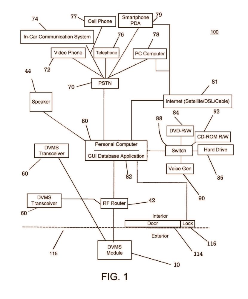
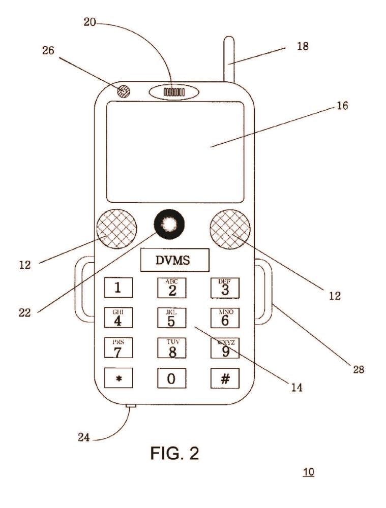
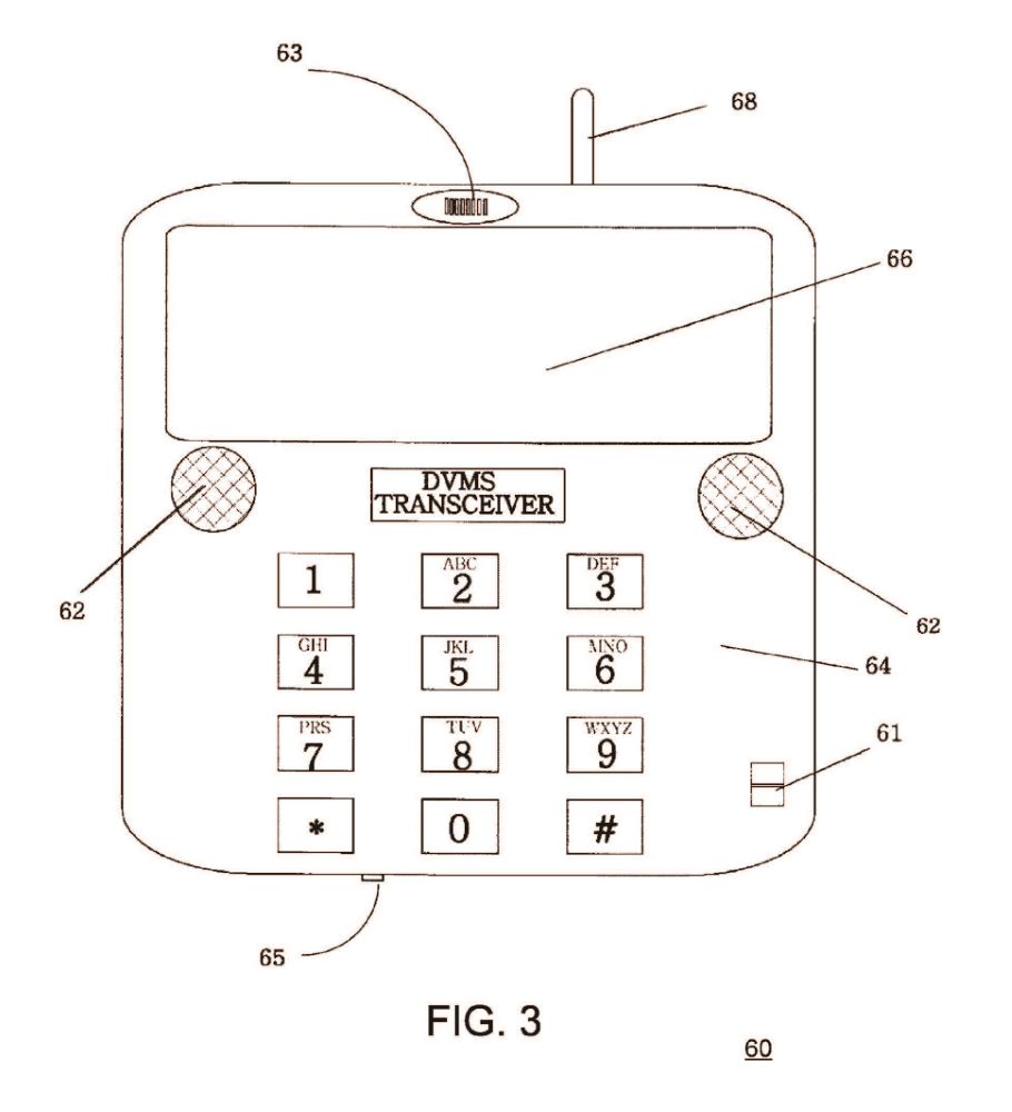
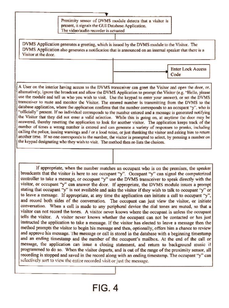
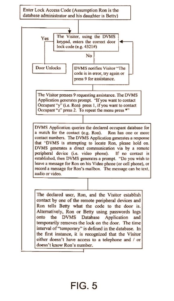
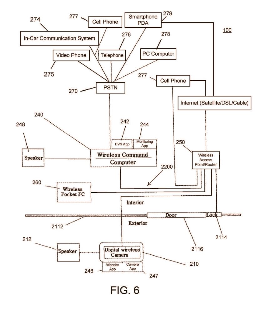
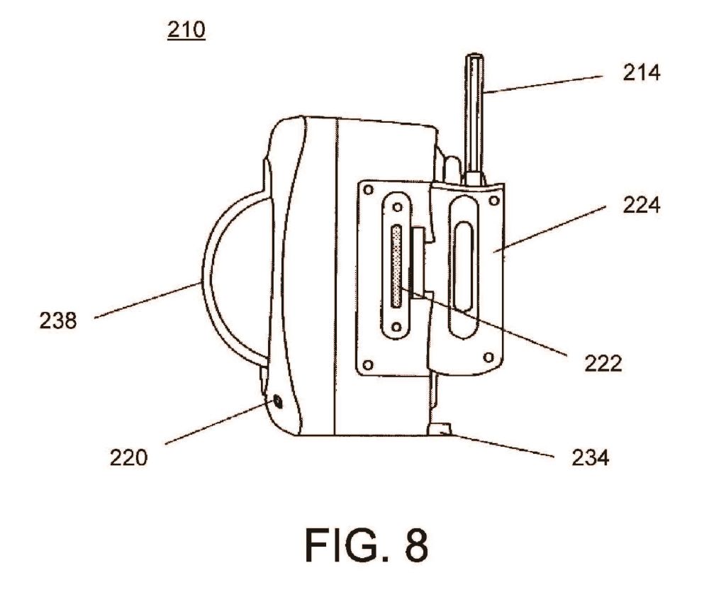


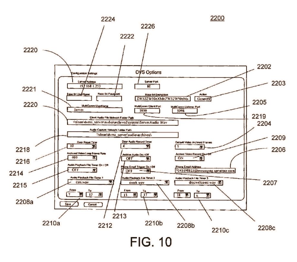
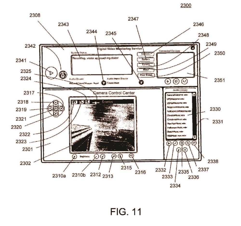
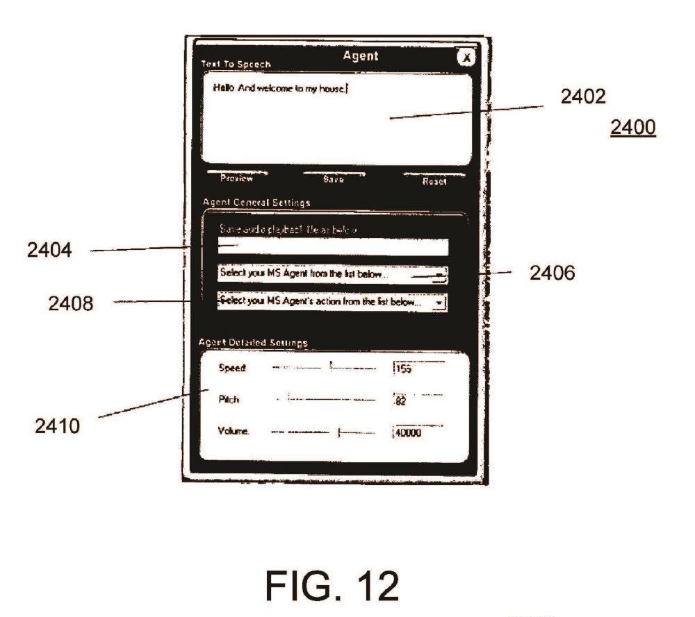
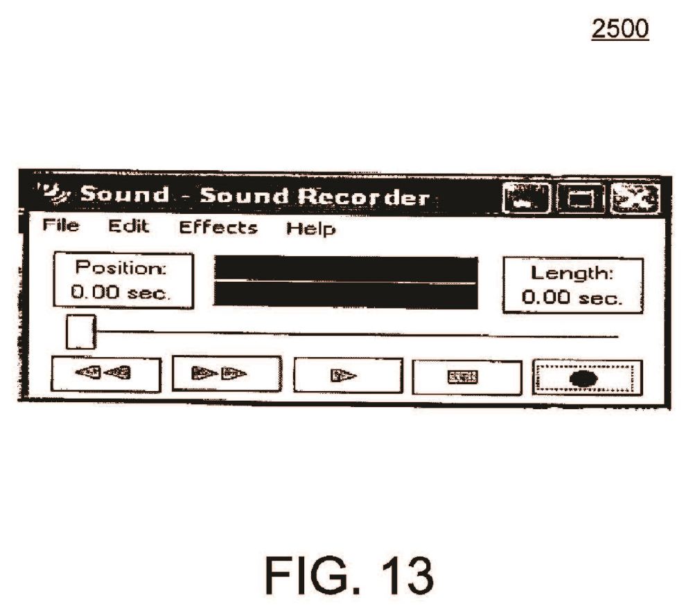
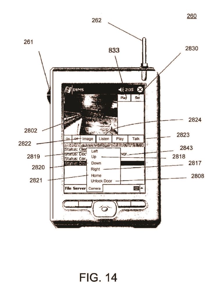
ABSTRACT
An audio-video communication system comprises a wireless exterior module located proximate an entrance, a computerized controller running a software application, and a remote peripheral device. The wireless exterior module includes a proximity sensor for detecting a person at the entrance, a video camera for recording an image of the person at the entrance, a microphone for recording the person at the entrance, a speaker for playing audio to the person at the entrance, a transmitter for communicating sounds and images of the person at the entrance, and a receiver for receiving communications at the wireless exterior module. The computerized controller is disposed in wireless electronic communication with the wireless exterior module via the transmitter and the receiver of the wireless exterior module. The remote peripheral device is configured to electronically communicate with the computerized controller for viewing an image from the video camera communicated from the wireless exterior module.
DESCRIPTION
I. CROSS REFERENCE TO RELATED APPLICATION
This application is a continuation-in-part patent application of, and claims the benefit under 35 U.S.C. §120 to, U.S. patent application Ser. No. 10/682,185, filed Oct. 9, 2003, published as U.S. Patent Appl. Publication No. 2005/0285934 A1 and now granted as U.S. Pat. No. 7,193,644 which patent application is a nonprovisional patent application of U.S. patent application Ser. No. 60/418,384, filed on Oct. 15, 2002, expired. Each of these patent applications, patent application publication, and patent is hereby incorporated herein by reference.
II. BACKGROUND OF THE INVENTION
There are numerous problems presently associated with receiving visitors at a home or office. When the resident of the home or occupant of the office (hereinafter generally referred to as either resident or occupant) is absent, there is often no message for the visitors, no means to leave an interactive message for the resident, and no means to ensure that unwanted access is not obtained. Moreover, answering the call of someone at a door of a dwelling can present certain security risks to an occupant therein. This situation can be especially inconvenient when, for example, a delivery or repair person arrives and the resident is not present. When the resident is present, on the other hand, there are also problems associated with receiving visitors. Some visitors may be unwelcome, for example, and it is often not evident that a visitor is a threat or an annoyance until after the door is open.
There are many types of systems for receiving a person by an occupant or resident and/or on the behalf of the occupant or resident. Such systems include those disclosed in each of: U.S. Pat. No. 5,148,468 titled “Door Answering System”, which issued Sep. 15, 1992 to Marrick et al; U.S. Pat. No. 5,303,300 titled “Security Door Phone Device,” which issued Apr. 12, 1994 to Eckstein; U.S. Pat. No. 5,406,618 titled “Voice Activated, Hands Free Telephone Answering Device,” which issued Apr. 11,1995 to Knuth, et al.; and U.S. Pat. No. 5,657,380 titled “Interactive Door Answering and Messaging Device with Speech Synthesis,” which issued to Mozer on Aug. 12, 1997. Nevertheless, a need remains for further improvement in such a system.
III. SUMMARY OF THE INVENTION
The invention includes many aspects and features. Moreover, while many aspects and features of the invention relate to, and are described in, the context of a system for receiving a person at an entrance, such as, an entrance to a home or business, the invention is not limited to use only in such context and may be used and has applicability in other contexts as well.
In one aspect of the invention, an audio-video communication system comprises a wireless exterior module located proximate an entrance, a computerized controller running a software application and a remote peripheral device. The wireless exterior module includes a proximity sensor for detecting a person at the entrance, a video camera for recording an image of the person at the entrance, a microphone for recording sound of the person at the entrance, a speaker for playing audio to the person at the entrance, a transmitter for communicating sounds and images of the person at the entrance, and a receiver for receiving communications at the wireless exterior module. The computerized controller is disposed in wireless electronic communication with the wireless exterior module via the transmitter and the receiver of the wireless exterior module. The computerized controller is configured to control recording of communications with the wireless exterior module and playback of such recording, and the software application includes a graphic user interface that enables a user to view images from the video camera communicated from the wireless exterior module. The remote peripheral device is configured to electronically communicate with the computerized controller for viewing an image from the video camera communicated from the wireless exterior module.
In a feature of the first aspect, the audio-video communication system further comprises a second wireless exterior module located proximate an entrance, with the second wireless exterior module having a proximity sensor for detecting a person at the entrance, a video camera for recording an image of the person at the entrance, a microphone for recording sound of the person at the entrance, a speaker for playing audio to the person at the entrance, a transmitter for communicating sounds and images of the person at the entrance, and a receiver for receiving communications at the wireless exterior module. The computerized controller running the software application is further disposed in wireless electronic communication with the second wireless exterior module via the transmitter and the receiver of the second wireless exterior module.
In another feature of this aspect, the remote peripheral device is configured to remotely actuate the camera of the wireless exterior module. In an additional feature, the graphic user interface enables a user to view streaming video with the remote peripheral device. In yet another feature, the remote peripheral device comprises a cell phone. In still yet another feature, the remote peripheral device comprises a video phone. In further features, the remote peripheral device comprises a computer and a personal digital assistant.
In an additional feature, the entrance comprises an entrance of a business. In another additional feature, the entrance comprises an entrance of a residence. In a further feature, the wireless exterior module includes a display screen. In still a further feature, the wireless exterior module includes a keypad comprising a touch screen or a keyboard. In yet a further feature, the wireless exterior module is portable and includes a locking mechanism and an electrical receptacle for quickly attaching to a source of electricity.
In another feature, the wireless exterior module has a portable energy source and is secured in a holster. In yet another feature, the computerized controller comprises a personal computer. In still yet another feature, the computerized controller is disposed in electronic communication with a public switching telephone network (PSTN).
In a further feature, the computerized controller is disposed in electronic communication with the Internet. In an additional feature, the audio-video communication system further comprises an electronically actuated lock that is configured to be unlocked by the computerized controller. In another feature, the system further comprises a voice recognition system.
In still a further feature, a transceiver includes the transmitter for communicating sounds and images of the person at the entrance and the receiver for receiving communications at the wireless exterior module. In yet another feature, the computerized controller includes an image recognition module for identifying at least one of faces, eyes, and fingerprints.
In a second aspect of the invention, a method for two-way audio-video communications between a first person at an entrance and a second person comprises the steps of (a) detecting, with a proximity sensor located proximate an entrance, the presence of a first person at the entrance; and (b) providing real time audio-video communications between the first person at the entrance and a second person using a wireless handheld device. Step (b) is done by (i) transmitting, to the wireless handheld device of the second person, video of the first person at the entrance recorded using a camera located proximate the entrance, (ii) transmitting, to the wireless handheld device of the second person, audio of the first person at the entrance recorded using a microphone located proximate the entrance, and (iii) transmitting, to a speaker located proximate the entrance for playing to the first person at the entrance, audio of the second person recorded using the wireless handheld device.
In a feature of this aspect, the transmitting includes wireless communications between both the camera and microphone located proximate the entrance and a computerized controller running a software application including a graphic user interface by which the audio-video communications between the first person and the second person are established. In another feature, the method further comprises the step of playing a recorded greeting to the first person at the entrance upon the detection of the first person at the entrance with the proximity sensor. With regard to this feature, the method further comprises determining, by a user with a remote peripheral device, the recorded greeting that is played through a graphical user interface. With further regard to this feature, the recorded greeting is selected by the user from a plurality of recorded greetings. It accordance with this feature, the recorded greetings are seasonal greetings. It is preferred that the recorded greeting includes audio and video.
In an additional feature, the method further comprises the step of posting, by the user from a remote peripheral device, a video greeting for presentation to a first person at the entrance. In further features, the wireless handheld device comprises a cell phone, a video phone, and a personal digital assistant.
In yet another feature, the entrance comprises an entrance of a business. In still a further feature, the entrance comprises an entrance of a residence. In another feature, the method further comprises the step of saving a recording of the two-way audio-communications in a database for later playback. In yet another feature, the method further comprises transmitting, to a video display located proximate the entrance for presentation to the first person at the entrance, video of the second person recorded using the wireless handheld device.
In an additional feature, the transmitting includes communications over the Internet. In further features, the transmitting includes communications over a cellular network and over a satellite network. In yet another feature, the method further comprises remotely actuating the camera located proximate the entrance using the wireless handheld device. In still further features, the step of remotely actuating the camera includes zooming an image of the first person at the entrance and remotely moving the camera to change the view of the camera.
In a third aspect of the invention, a method for receiving a person at an entrance comprises the steps of (a) detecting, with a proximity sensor located proximate an entrance, the presence of a person at the entrance; (b) transmitting, to a computerized controller running a software application, video of the person at the entrance recorded using a camera located proximate the entrance; and (c) providing, with the application software running at the computerized controller, a graphic user interface to a remote peripheral device by which a user of the remote peripheral device may view the video of the person at the entrance.
In a feature of this aspect, the method further comprises the step of saving, in accordance with the application software running at the computerized controller, the video of the person at the entrance in a database in association with a timestamp. In other features, the video is viewed using the remote peripheral device in real-time, viewed using the remote peripheral device after the person at the entrance has left, and is streamed to the remote peripheral device.
In an additional feature, the method further comprises the step of transmitting, to the computerized controller running the software application, audio of the person at the entrance recorded using a microphone located proximate the entrance; wherein the graphic user interface provided to the remote peripheral device further enables a user of the remote peripheral device to hear the audio of the person at the entrance. In another feature, the method further comprises the step of playing a recorded greeting to the person at the entrance upon the detection of the person at the entrance with the proximity sensor.
In another feature, the method further comprises determining, by a user with the remote peripheral device, the recorded greeting that is played through a graphical user interface. With regard to this feature, the recorded greeting may be selected by the user from a plurality of recorded greetings, the recorded greetings may be seasonal greetings, and the recorded greeting may include audio and video.
In yet another feature, the method further comprises the step of posting, by the user from the remote peripheral device, a video greeting for presentation to a person at the entrance. In other features, the remote peripheral device comprises a cell phone, a video phone, a computer, and a personal digital assistant. In still other features, the entrance comprises an entrance of a business and an entrance of a residence.
In still another feature, the method further comprises remotely actuating the camera located proximate the entrance using the remote peripheral device. In further features, the step of remotely actuating the camera includes zooming an image of the person at the entrance and remotely moving the camera to change the view of the camera.
In addition to the aforementioned aspects and features of the present invention, it should be noted that the present invention further encompasses the various possible combinations of such aspects and features.
IV. BRIEF DESCRIPTION OF THE DRAWINGSOne or more preferred embodiments of the invention now will be described in detail with reference to the accompanying drawings.
FIG. 1 is a schematic diagram of a system in accordance with a preferred embodiment of the invention.
FIG. 2 is a planar view of the font of a DVMS module of the system of FIG. 1
FIG. 3 is a planar view of the front of a DVMS transceiver of the system of FIG. 1.
FIG. 4 is a block diagram overview of a method in accordance with a preferred embodiment of the invention.
FIG. 5 a block diagram extension of the method of FIG. 4.
FIG. 6 is a schematic diagram of a system in accordance with another preferred embodiment of the invention.
FIG. 7 is a perspective view of the front of a wireless network camera of the system of FIG. 6.
FIG. 8 is a side view of the wireless network camera of FIG. 7.
FIG. 9 is a perspective view of the rear of the wireless network camera of FIG. 7.
FIG. 10 is a representative screen view of a wireless command center of the system of FIG. 6, wherein various parameter settings for configuring, e.g., the audio, video, server, and cell phone options are illustrated.
FIG. 11 is a screen view of the normal operating mode interface of the wireless command center of FIG. 10, wherein a user is able to dynamically control a wireless network camera, view video images generated by the wireless network camera, listen and send both pre-canned and live audio files, and review archived system events.
FIG. 12 is a dialog box screen view of the text-to-voice synthesizer module of the wireless command center of FIG. 10.
FIG. 13 is a dialog box screen view of the recorded voice synthesizer module of the wireless command center of FIG. 10.
FIG. 14 is a planar view of the front of a wireless pocket PC that is connected to a wireless network, wherein a user of the wireless pocket PC is able to dynamically control the wireless network camera, view video images generated by the wireless network camera, listen and send both pre-canned and live audio files, and review archived system events in the system of FIG. 6.
V. DETAILED DESCRIPTION
As a preliminary matter, it will readily be understood by one having ordinary skill in the relevant art (“Ordinary Artisan”) that the present invention has broad utility and application. Furthermore, any embodiment discussed and identified as being “preferred” is considered to be part of a best mode contemplated for carrying out the present invention. Other embodiments also may be discussed for additional illustrative purposes in providing a full and enabling disclosure of the present invention. Moreover, many embodiments, such as adaptations, variations, modifications, and equivalent arrangements, will be implicitly disclosed by the embodiments described herein and fall within the scope of the present invention.
Accordingly, while the present invention is described herein in detail in relation to one or more embodiments, it is to be understood that this disclosure is illustrative and exemplary of the present invention, and is made merely for the purposes of providing a full and enabling disclosure of the present invention. The detailed disclosure herein of one or more embodiments is not intended, nor is to be construed, to limit the scope of patent protection afforded the present invention, which scope is to be defined by the claims and the equivalents thereof. It is not intended that the scope of patent protection afforded the present invention be defined by reading into any claim a limitation found herein that does not explicitly appear in the claim itself.
Thus, for example, any sequence(s) and/or temporal order of steps of various processes or methods that are described herein are illustrative and not restrictive. Accordingly, it should be understood that, although steps of various processes or methods may be shown and described as being in a sequence or temporal order, the steps of any such processes or methods are not limited to being carried out in any particular sequence or order, absent an indication otherwise. Indeed, the steps in such processes or methods generally may be carried out in various different sequences and orders while still falling within the scope of the present invention. Accordingly, it is intended that the scope of patent protection afforded the present invention is to be defined by the appended claims rather than the description set forth herein.
Additionally, it is important to note that each term used herein refers to that which the Ordinary Artisan would understand such term to mean based on the contextual use of such term herein. To the extent that the meaning of a term used herein—as understood by the Ordinary Artisan based on the contextual use of such term—differs in any way from any particular dictionary definition of such term, it is intended that the meaning of the term as understood by the Ordinary Artisan should prevail.
Furthermore, it is important to note that, as used herein, “a” and “an” each generally denotes “at least one,” but does not exclude a plurality unless the contextual use dictates otherwise. Thus, reference to “a picnic basket having an apple” describes “a picnic basket having at least one apple” as well as “a picnic basket having apples.” In contrast, reference to “a picnic basket having a single apple” describes “a picnic basket having only one apple.”
When used herein to join a list of items, “or” denotes “at least one of the items,” but does not exclude a plurality of items of the list. Thus, reference to “a picnic basket having cheese or crackers” describes “a picnic basket having cheese without crackers”, “a picnic basket having crackers without cheese”, and “a picnic basket having both cheese and crackers.” Finally, when used herein to join a list of items, “and” denotes “all of the items of the list.” Thus, reference to “a picnic basket having cheese and crackers” describes “a picnic basket having cheese, wherein the picnic basket further has crackers,” as well as describes “a picnic basket having crackers, wherein the picnic basket further has cheese.”
Referring now to the drawings, one or more preferred embodiments of the present invention are next described. The following description of one or more preferred embodiments is merely exemplary in nature and is in no way intended to limit the invention, its applications, or uses.
The System of FIG. 1
FIG. 1 is a schematic diagram of a system 100 in accordance with a preferred embodiment of the invention. For purposes of providing an enabling description, the system 100 is described in the context of a door answering system for receiving a person at a home or office and is capable of controlling access to the home or office. In FIG. 1, the exterior of the home or office is differentiated from the interior by demarcation line 115, which represents a wall or other similar structure. The wall 115 includes an entrance in the form of a door 114 and an electronically actuated lock 116 for selectively locking and unlocking the door 114.
A computerized controller in the form of a personal computer 80 is disposed in the interior and is configured to selectively actuate the lock 116. The personal computer 80 preferably includes a DVD-R/W 84, a CD-ROM R/W 92, and a hard drive 86. One or more of these components 84,92,86 of the personal computer 80 preferably are utilized for recording video and audio communications that are transmitted to and from the DVMS module 10 (described in further detail below) and for playing video and audio communications that are stored via the personal computer 80.
The personal computer 80 also may include a voice generator 90 for use in generating prompts, which either exists as pre-recorded messages or are generated by a voice synthesizer. Each of these components 84,92,86,90 of the personal computer 80 may be separately disposed from the personal computer and connected, for example, by a switch 88, or may form part of the personal computer 80 and be disposed in electronic communication with a bus of the personal computer 80 within the housing thereof.
A speaker 44 is disposed in electronic communication with the personal computer 80. The speaker 44 is not shown as being wireless, but could be. Moreover, one speaker 44 is shown, but additional speakers could be used in the system 100. Furthermore, speaker 44 in FIG. 1 is represented as being separate from the personal computer 80, however, the speaker 44 could alternatively form part of the personal computer 80.
The personal computer 80 preferably is disposed in electronic communication with the Internet. The connection with the Internet preferably is accomplished by a broadband connection such as a connection 81 provided by a satellite modem, a DSL model, or a cable modem, or any combination thereof.
The personal computer 80 also preferably is connected to a public switching telephone network (PSTN) 70, which enables communication by and with the personal computer 80 via standard telephone lines.
The personal computer 80 preferably has a battery backup as well as a means for detecting a loss in electrical power such that, when electrical power is lost the battery backup will provide sufficient operating time for the personal computer 80 to notify someone responsible for the maintenance of the system that there has been a loss of electricity. Notification of the loss of electricity can be important, since the loss of electrical power can be an indication of a burglary. Additionally, if there is no electricity, then appliances, such as refrigerators, air conditioners, and heaters, cannot function and significant damage can results if the electrical failure goes undetected for a substantial period of time.
The personal computer 80 runs a software application that includes a DVMS Database Application 82 and graphic user interfaces (GUIs). The personal computer 80, in accordance with the software application, controls communication in the system 100, coordinates multiple communication devices in the system 100, and is used to define responses to prompts and events in the system 100. The DVMS Database Application 82 and its uses are described in greater detail below.
The system 100 further includes a wireless router 42 located in the interior. The wireless router 42 in FIG. 1 is represented as being separate from the personal computer 80, however, the wireless router 42 could alternatively form part of the personal computer 80. The wireless router 42 is used to establish a wireless network and is disposed in electronic communication with the personal computer 80.
The system 100 also includes a DVMS module 10 located on the exterior of the home or office proximate the door 114. The DVMS module 10 is configured for use in the exterior of the home or office, which may include outdoor use in external residential or commercial locations. The DVMS module 10 is disposed in wireless communication with the wireless network, including the personal computer 80, via the wireless router 42.
With reference to FIG. 2, the DVMS module 10 preferably includes: a video camera 22; speakers 12; a proximity sensor 26; a microphone 20; an LCD display 16; a quick connect electrical receptacle 24; and a radiofrequency receiver/transmitter represented by antenna 18. The proximity sensor 26 activates the camera 22 upon detection of movement, which in turn relays an image or streaming video to the personal computer 80 where it is saved by the personal computer 80 in a database in association with a timestamp. Operation of the system is described in further detail below.
The DVMS module 10 optionally includes a small portable energy source, such as a battery that is rechargeable via the quick connect electrical receptacle 24, for portable use as well as for use in the event of a power failure.
The LCD display 16 screen preferably is a low energy screen reducing energy consumption. The LCD display 16 preferably comprises a touch screen and can be used to send and receive text similar to a keypad. Alternatively, or in addition thereto, the DVMS module 10 includes a keypad 14. In either case, the DVMS module 10 enables text messaging by a person at the exterior, which in turn enables a private non-audible conversation to be had and eliminates risks of eavesdropping by a passerby.
The DVMS module 10 also includes a locking mechanism 28 for receipt in a mounting holster (not shown). The locking mechanism 28 enables the DVMS module 10 to be installed securely wherever holstered, or to be moved to some other remote location, as desired. The DVMS module 10 thus is portable, much like a cell phone, and can be securely mounted and quickly connected to an electrical source.
It is anticipated that there could be multiple entrances to the home or office and, similarly, multiple DVMS modules similar to DVMS module 10 of FIG. 2 could be utilized, each disposed in wireless communication with the wireless network via the wireless router 42.
The system optional includes one or more DVMS transceivers 60. The DVMS transceivers 60 is configured for use in the interior of the home or office. As illustrated in FIG. 1, a DVMS transceivers 60 may be disposed in wireless communication with the wireless network, including the personal computer 80, and the DVMS module 10, via the wireless router 42. Additionally or alternatively, a DVMS transceivers 60 may be configured to wirelessly communicate directly with the DVMS module 10, thus bypassing communications through the wireless router 42.
With reference to FIG. 3, each DVMS transceiver 60 is portable and, like the DVMS module 10, the DVMS transceiver 60 communicates by short-range radiofrequency transmissions. The DVMS transceiver 60 includes: speakers 62; a microphone 63; an LCD display 66; a quick connect electrical receptacle 65; and a radiofrequency receiver/transmitter represented by antenna 68. The DVMS transceiver 60 optionally includes a small portable energy source, such as a battery that is rechargeable via the quick connect electrical receptacle 65, for portable use as well as for use in the event of a power failure. The DVMS transceiver 60 further includes a mute switch 61, which cuts-off the microphone 63, thus assuring a user of the DVMS transceiver 60 that a visitor can be monitored using the DVMS transceiver 60 without inadvertently sending an audible signal fro the user.
The LCD display 66 screen preferably is a low energy screen reducing energy consumption. The LCD display 66 preferably comprises a touch screen and can be used is used to send and receive text similar to a keypad. Alternatively, or in addition thereto, the DVMS transceiver 60 includes a keypad 64. In either case, the DVMS module 60 enables text messaging by a user of the DVMS transceiver 60 with a person at the exterior using the DVMS module 10, which in turn enables a private non-audible conversation to be had and eliminates risks of eavesdropping by a passerby.
The system 100 further includes one or more remote peripheral devices. Such devices generally include video phones 72; in-car communication systems such as the well known ONSTAR system 74 currently found in GM cars; telephones 76; cell phones 77; personal computers 78; smartphones/personal digital assistants (PDAs) 79; and other similar communication devices. Each remote peripheral device is configured for electronic communication with the personal computer 80 via at least the PSTN connection 70 or the broadband connection 81.
As mentioned above, the personal computer 80 runs a software application that includes a DVMS Database Application 82 and graphic user interfaces (GUIs). The software application is configured and maintained by an administrator, who defines users thereof. The users in the system 100 are referred to as “occupants” reflecting their relation to the home or office.
Preferably, the occupants have various levels of access to the software application, depending on the privileges set by the administrator. The administrator may also set a level of security under which the system is to operate, particularly with respect to connections made using remote peripheral devices.
Other examples of configuration settings of the software application that are determined by the administrator include: aliases for a declared occupant such as, e.g., “Daddy” or “Momma”; passwords to access the software application; access codes to actuate the electronic lock controlled by the computerized controller; a number or other identifier that corresponds to an occupant's name; and at least one telephone number by which an occupant can be reached. The administrator also preferably defines a preferred hierarchy of storage of audio and video data, the location and number of backup devices, and whether replications of the database are to be kept.
Additionally, when setting up the software application, the administrator chooses, inter alia: a prompt for greeting a visitor; chooses an announcement that is to be given over a speaker within the interior when a visitor arrives; a prompt for requesting information from a visitor; a request instructing a visitor as to their choices in leaving a message or contacting a declared user; and the action that is to be performed by the computerized controller based on the input by the visitor.
The administrator also tailors the security/premise monitoring response by, inter alia: designating telephone numbers that the computerized controller calls when, for example, there is a loss of power; and designating telephone emergency numbers (e.g., telephone numbers for the police, the fire department, relatives, private security companies) that the computerized controller calls when an emergency is detected. The computerized controller also conducts self checks to confirm that all the components of the system are operational and keeps a log of the self checks, and the computerized controller preferably calls one or more designated numbers when a self check indicates a failure or otherwise improper operation.
The software application also can be configured to play background music or videos at different times of the year and/or different times of the day to reflect seasonal holidays, birthdays, and events. For instance, on Halloween the administrator may wish to have scary music and howls issuing from the DVMS module for receiving a person at that time. Furthermore, utilizing the computerized controller, the administrator can choose to use default prompts for interacting with a visitor or create customized prompts.
As hardware is added, such as the number of the DVMS modules and DVMS transceivers, the administrator can update both the network to include the additional devices and the computerized controller to accommodate the additional devices.
The software application also is configured to send voice, text, and video messages via email. The administrator can further set up redundant subsystems of the system 100.
The system 100, in use, enables secure and effective monitoring and interacting with a visitor at a residence or business, including, inter alia: the detection of the presence of a visitor at the exterior of the home or office via the proximity sensor 26, the interactive communication with the visitor, whether an occupant is present or absent from the home or office, the enablement of automated entry into the home or office by the visitor, and personalization of the process of receiving a visitor.
An exemplary method of use in the system 100 includes greeting and communicating with visitors of a business or residence. In accordance with the method, the presence of a visitor is detected via the proximity sensor 26 of the DVMS module 10, where the DVMS module 10 is mounted at or near an entrance to the business or residence. Upon the detection of the visitor by the proximity sensor 26, a message is communicated to the personal computer 80 from the DVMS module 10 indicating the detection of a visitor at the entrance. A recording is actuated by the personal computer 80, and the recording is stored in a computer-readable medium such as a database along with a beginning time-stamp. The arrival of a visitor is broadcast over a speaker within the home or office, such as speaker 44. An occupant can view the visitor on a display on the DVMS transceiver 60 or on a display of the personal computer 80, and the occupant can initiate a conversation at any time. The DVMS module 10 issues a greeting to the visitor and instructs the visitor to select a number from the keypad 14 of the DVMS module 10 in order to designate the occupant being visited. The entered number is communicated from the DVMS module 10 to the personal computer 80, where the software application confirms that the number corresponds to an occupant “y” who is “officially” present. An error message is generated if no individual corresponds to the number entered by the visitor. If no individual corresponds to the number entered by the visitor, then the visitor is prompted to select and press another number on the keypad 14 again designating the occupant being visited. The method then lists the choices again.
While this is going on, the door may be answered at any time, thereby resetting the software application to look for another visitor. The software application keeps track of the number of times a wrong number is entered and can generate a variety of responses to pranks, including calling the police, issuing warnings and/or a loud noise, or just thanking the visitor and asking him to return another time.
If appropriate, when the number designated by the visitor matches an occupant who is officially on the home or office, the speaker broadcasts that the visitor is here to see occupant “y”. Occupant “y” can signal the personal computer 80 to take a message, or occupant “y” may choose to use the DVMS transceiver 60 to speak directly with the visitor, or occupant “y” can answer the door.
If appropriate, the DVMS module 10 issues a prompt stating that occupant “y” is not available and asks the visitor if they wish to speak to occupant “y” or to leave a message.
If appropriate, at any time the software application can initiate a call to occupant “y” via a remote peripheral device for communication between occupant “y” and the visitor, and the software application can record both sides of the conversation between occupant “y” and the visitor. The occupant can view the visitor or initiate a conversation, as the occupant desires. A visitor never knows where the occupant is, unless the occupant tells the visitor of the occupant's location. A visitor also never knows if the occupant can be contacted, or if the occupant has just instructed the application to take a message. Using the method the conversation or messages can be relayed to the selected occupant without the visitor ever knowing where the location of the occupant. Only the occupant can disclose such location to the visitor as desired.
If the visitor elects to leave a message, then the method prompts the visitor to begin his message and then, optionally, offers him a chance to review and approve his message. The message or call is stored in computer readable medium, such as database, by the personal computer 80 in association with a beginning timestamp and an ending timestamp along with the occupant's mailbox number. At the end of the call or message, the software application can issue a closing statement and return to background music, if programmed to do so.
When the visitor departs, and is out of the range of the proximity sensor 26, all recording is stopped and saved in the database record, along with an ending timestamp. The occupant “y” can selectively sort to view the entire recorded visit, or just the message.
If the proximity sensor 26 indicates that there is another visitor, the method cycles back to the greeting step.
If the system has an electronically actuated lock, then the method also may include the steps of checking the number entered by the visitor to determine if it is a valid access code. The electronically actuated lock may be unlocked by entering an access code either at the DVMS module 10 or remotely therefrom. If the number is valid, then the lock is actuated, and if the number is not valid, then a prompt is made requested that the code be re-entered. Optionally, the prompt may further request a number be entered that corresponds to one of the occupants if assistance is needed and, if an occupant is selected, then calling the selected occupant. The method also may include tracking how many times the wrong code is entered; checking if the maximum allowed number of wrong entries have been made; and, when the maximum number of wrong entries is reached, either automatically calling a designated party and/or removing access privileges.
An occupant preferably has the option of remotely entering the access code, thereby actuating the electronically actuated lock, or instructing the GUI database application to go to a new high security level, wherein the lock cannot be accessed and notifying the visitor that the access code is not operational.
In the method, upon the entering of a valid access code assigned to a declared occupant, the software application optionally notifies the administrator or his designated representative that the declared occupant has now entered the home or office. The administrator would know who the individual should be. The administrator thus can confirm, by remotely viewing the recorded video, that the actual person who entered the access code is the declared occupant, and/or make a follow-up telephone call to the home or office. The system 100 also provides the options of allowing the visitor to converse with the occupant, leaving a message, or calling a remote peripheral device for communication with the occupant when he is either not present or is unavailable. The entrance is recorded and time stamped for sorting or viewing either in real time or at a later date.
The system 100 further enables the administrator or a declared occupant to, at any time, to turn on a camera and view images, access the recorded the video images, or post a video image from a remote peripheral device to computerized controller including associated components.
The system 100 preferably is inherently extensible in both form and function and is designed so that the system can be expanded to include multiple peripheral devices, both in direct and indirect communication with the computerized controller. Due to the use of the computerized controller and its interconnectivity, the disclosed system 100 can be configured to accommodate communications having a range of complexity.
As will be apparent from the foregoing, the system 100 provides an audio-video communication and answering system that provides real time communication between an exterior of a business or residence and an interior of the business or residence as well as a location remotely located to the business or residence.
As will be apparent from the foregoing, the system 100 provides an audio-video communication and answering system that provides real time communication between two or more rooms at a home or office and a remote location.
As will be apparent from the foregoing, the system 100 provides an audio-video communication and answering system that provides the ability to leave messages at a centralized location from a local or remote location.
In addition to the foregoing description of a method, FIG. 4 shows a block diagram illustrating an example of the use of a system of the invention as a door answering and messaging system at a residence. Furthermore, FIG. 5 shows a block diagram illustrating an example of the use of a system of the invention as a door answering and messaging system at a residence, wherein the system includes an electronically actuated lock. In the example, an occupant is attempting to gain access to the home or office.
As will now be apparent, systems in accordance with the invention achieve one or more of the foregoing benefits and features yet remain intuitive and easy to use.
In addition to the foregoing, it further is anticipated that, in certain deployments of the invention, voice recognition would be useful, particularly when the system enables access to a home or office. Voice recognition adds another layer of security, and can be used to facilitate those individuals who are unable to press a keypad. Similarly, image recognition of faces, eyes and fingerprints can also be included in the system for authentication, security, and access. The software application thus alternatively utilizes voice recognition and/or image recognition.
Furthermore, while no camera is shown located within the home or office, any number of cameras could be utilized on the interior.
It will also be appreciated that a business may be a tenant located within a building shared by other businesses. A DVMS module for the business thus would be utilized on the exterior of the business, i.e., at the “front door” of the business, which would be located within the interior of the common building.
In variations of systems of the invention, it should further be noted that one or more devices having the functionality of DVMS modules could be utilized in the interior for securing entrance to a room or group of rooms.
The System of FIG. 6
FIG. 6 is a schematic diagram of a system 2100 in accordance with another preferred embodiment of the invention. The system 2100 includes: a local area network 2200; a wireless digital camera 210; and a computerized controller in the form of a personal computer 240 (identified as the “Wireless Command Computer” in FIG. 6). The lines indicate communications between member devices and components of the system 2100 and such communications may be wired, wireless, or a combination of both wired and wireless. For purposes of providing an enabling description, the system 2100 is described in the context of a door answering system for receiving a person at a home or office and is capable of controlling access to the home or office. In FIG. 6, the exterior of the home or office is differentiated from the interior by a wall 2112 or other similar structure. The wall 2112 includes an entrance in the form of a door 2116 and an electronically actuated lock 2114 for selectively locking and unlocking the door 2116.
The personal computer 240 is disposed in the interior and is configured to selectively actuate the lock 2114. The personal computer 240 includes one or more components utilized for recording video and audio communications and for playing video and audio communications. The personal computer 240 also may include a voice generator for use in generating prompts, which either exists as pre-recorded messages or is generated by a voice synthesizer. Each of these components of the personal computer 240 may be separately disposed from the personal computer and connected, for example, by a switch, or may form part of the personal computer 240 and be disposed in electronic communication with a bus of the personal computer 240 within the housing thereof. A speaker 248 is disposed in electronic communication with the personal computer 240. Moreover, one speaker 248 is shown, but additional speakers could be used in the system 2100. Furthermore, speaker 248 in FIG. 6 is represented as being separate from the personal computer 240, however, the speaker 248 could alternatively form part of the personal computer 240.
The personal computer 240 preferably is disposed in electronic communication with the Internet. The connection with the Internet preferably is provided by a broadband connection through, for example, a wireless router 250. Such broadband connection may be accomplished by a satellite modem, a DSL model, or a cable modem, or any combination thereof. The personal computer 240 also preferably is connected to a public switching telephone network (PSTN) 70, which enables communication by and with the personal computer 240 via standard telephone lines.
The personal computer 240 preferably has a battery backup as well as a means for detecting a loss in electrical power such that, when electrical power is lost the battery backup will provide sufficient operating time for the personal computer 240 to notify someone responsible for the maintenance of the system that there has been a loss of electricity. Notification of the loss of electricity can be important, since the loss of electrical power can be an indication of a burglary. Additionally, if there is no electricity, then appliances, such as refrigerators, air conditioners, and heaters, cannot function and significant damage can results if the electrical failure goes undetected for a substantial period of time.
With regard to the wireless router 250, it is represented as being separate from the personal computer 240, however, the wireless router 42 could alternatively form part of the personal computer 240. The wireless router 42 is used, inter alia, to establish a wireless network and is disposed in electronic communication with the personal computer 240. The router 250 is WiFi compliant, and operates using a standardized protocol such as, for example, 802.11(b) and/or 802.11(g).
The wireless router 250 facilitates two-way communication over the local area network 2200 among the member devices and components of the wireless network 2200. Furthermore, the wireless router 250 preferably is disposed in electronic communication with the Internet and facilitates two-way communication between the member devices and components of the wireless network 2200 and remote devices communicating over the Internet. Such remote devices generally include video phones 275; in-car communication systems, such as the well known ONSTAR system 274 currently found in GM cars; telephones 276; cell phones 277; personal computers 278; smartphones/personal digital assistants (PDAs) 279; and other similar communication devices. Each remote device preferably is configured for electronic communication with one or more of the member devices and components of the wireless network 2200 via at least the PSTN connection 270 or a broadband Internet connection. Additionally, a remote device may be configured to communicate with one or more of the member devices and components of the wireless network 2200 via direct wireless communications with the wireless router 250 when such remote device is within communications range of the wireless router 250. Such direct wireless communications with the wireless router 250 is illustrated with the cell phone 277 in FIG. 6.
The wireless command computer includes a digital video system application (“DVS App”) 242 and a monitoring application 244. The DVS App 242 provides a set of customizable operating parameters for the wireless digital camera 210. The set of digital video operating parameters may include parameters selected from the group of: a default camera position; a number of frames per second; sensitivity and threshold of a motion sensor; length of a session; frequency of motion detection; and sensitivity and threshold of the motion detector. These parameters are conveyed to the camera operation application, discussed in further detail below. The monitoring application 244 includes a camera control screen that displays the camera webpage; and an operating screen that displays a set of operating parameters. The set of operating parameters may include parameters selected from the group of: a card file for cross-referencing MAC ID'S with cameras and pocket PCs on the wireless network; paths for logging and archiving files received from the camera; camera webpage addresses; email addresses for users; telephone numbers for cell phones; a designated greeting when a motion sensor is triggered; and security parameters. The monitoring application 244 further includes an audio library screen that displays the contents of a library of pre-recorded audio files. Typically, at least one pre-recorded audio file is a greeting audio file. In the context of the system 2100, the audio file can be sent over the local area network 2200, and can include, for instance, sounds, music, voice recordings, synthesized noises, and the like. The means of generating an audio file can be a microphone that feeds to an AID converter, which creates a digital audio file, such as a wav file or MP3 file, or a voice synthesized digital audio file. The monitoring application 244 generally includes a means of generating an audio file, and a command computer website that provides a command webpage with graphic controls for reviewing archived files. The monitoring application can further include a set of monitoring parameters that define the criteria for keeping or deleting a video file in memory, wherein the criteria includes available memory on system, age of file, and priority. The monitoring application also can further include an option to designate that the digital camera transmit video and audio data to more than one member device of the wireless network, and/or to split up audio and video data to two or more member devices. This feature is desirable if, for instance, it is preferred that either audio or video not be sent, or if a network member device—for instance a cell phone—is not configured to process both audio and video data. The monitoring application 244 also can include settings for notifying one or more designated individuals or a security service if an alarm is activated or if a predetermined condition is otherwise detected by a sensor. Such sensors may include, for example, smoke detectors, carbon monoxide detectors, laser beam detectors, broken window detectors, temperature detectors, radiation detectors, radon detectors, open window, door detectors, or a combination thereof. Moreover, such sensors may communicate via the local area network 2200.
The system 2100 includes a wireless digital camera 210 located on the exterior of the home or office proximate the door 2116. The wireless digital camera 210 includes a website application 246 and a camera operation application 247. The wireless digital camera 210 is shown in further detail in FIGS. 7-9. The wireless digital camera 210 preferably creates a series of images that are stored as a series of jpeg files which are displayed on a webpage of a website application 246 that is unique to a given camera 210. The camera 210 also includes a microphone 218, and the sound recorded by the microphone is digitized as an audio file, such as a .wav file or an MP3 file, that is transmitted along with the video as an audio file. This camera 210 preferably has a splash resistant body 225, a lens cover 238 over lens 216, and a wireless transceiver for audio 2-way audio communication. Furthermore, this camera 210 can pan, tilt, or move to a pre-set position. The camera 210 includes a motion sensor that triggers video recording with surveillance image quality, refreshing its image 30 frames per second, and includes a charge coupled device sensor to compensate for low light conditions. Communications via the wireless camera 210 also preferably are encrypted. The splash resistant body 225 allows the camera 210 to be used indoors or outdoors. The camera 210 also supports IPv6 (Internet Protocol Version 6). The audio feature of the camera 210 uses a Java applet that is installed during the installation. The camera 210 has a memory card 222 that is protected by a sealing door 224, a proximity detector or motion sensor 220, a microphone 218, a power input 226, an external microphone port 230, a LAN port 236, and a speaker port 232. The illustrated camera 210 has four mounting legs 234 and a mounting stand hole 235. The antenna 214 projects from the rear of the camera. A suitable wireless digital camera that has weather resistance is the camera currently sold in the United States by Panasonic under the part number BB-HCM371.
Every camera in the system 2100 preferably can be uniquely identified by a media access control (MAC) address that enables the personal computer 240, and each device in the system 2100 having a web browser, such as, e.g., a Windows Internet Explorer browser, or a Firefox browser, to be in wireless communication with camera 210 through the wireless router 250. While only one camera 210 is shown in FIG. 6, multiple cameras can be included in the system 2100, each with its own unique website accessible by multiple devices in the system 2100 having Internet browsers. In addition to displaying the video and audio on the camera's webpage, the website application 246 of the camera 210 displays graphic controls for actuating the camera 210, such as panning right and left, up and down, zoom in and zoom out, and adjustments for the amount of ambient light. These controls are illustrated in FIG. 11.
As previously stated, the camera 210 has a motion sensor 220 for detecting the presence of a person or a moving object with an adjustable level of sensitivity and a trigger threshold for initiating video recording, and, optionally issuing a verbal response, such as a greeting. The verbal response is an audio file, which can reside in the camera's memory as well as in the personal computer, in which case the verbal response can be transmitted, via the local area network 2200, to the camera 210. The camera 210 typically has a pre-set or default position, which can be static or dynamic. For instance, the camera 210 can be programmed to pan back and forth through a pre-set cycle or to zoom in and out, or any combination thereof. The motion sensor 220 has parameters for setting the sensitivity and a trigger threshold for initiating video recording. Upon initiation, the camera automatically starts recording video, which is displayed on the camera webpage in the form of video images, typically in serial form. The recording further can be transmitted to the personal computer 240 for saving for later viewing. In an alternative embodiment, the camera does not include a motion sensor 220 in the form of an additional piece of hardware but, instead, detects motion via a software application that analyzes the video images. In this alternative, the camera 210 records images on a routine basis and, when motion is detected, a video recording is initiated and a verbal response optionally is provided. Such software can be executed at the personal computer 210 or can be executed at the camera 210 and form part of the camera application 247.
The website application 246 of the digital camera 210 provides a webpage with graphic controls for operating the camera and a viewing area for viewing video images. When activate for recording the camera 210 provides digital video images that are displayed on the webpage. The camera 210 can be activated manually or self-activated by the motion sensor 220 that detects the presence of a person or a moving object. The motion sensor 220 has an adjustable level of sensitivity and a trigger threshold for initiating video recording. The camera 210 has a memory cache for saving a designated number or series of transmitted video images. Typically, when activated for video recording, the camera also activates audio recording, which provides audio files on the webpage generated by the digital camera's microphone 218. The camera 210 also includes means including the speaker 218 for playing received audio files.
Referring to FIG. 10, the screen 2200 for setting the parameters of the DVS application 242 is illustrated. Communications over the local area network 2200 between the camera 210 and command computer 240 are established using a MAC address of the camera 210 and/or an IP address 2224 for the camera. The default port 2226 for communications is 80. The camera 210 recognizes an encrypted username and password 2202. The DVS application 242 encrypts the username 2224 and the password 2222, using the generator 2203, resulting in the encrypted version 2202. The hierarchical structure of the member devices of the wireless network is defined in 2220, 2219 and 2205. The command computer 240 designated is named “Server”, as shown in the Username textbox 2221. The client port for uploading audio files 2219 is given as port 5999. An example of a client is a pocket PC 260 or cell phone 277 having a web browser. The listener port 2205 for down loading audio files is port 5998. The camera 210 has access to the audio files in a network-shared folder having a designated path 2220. When a greeting/verbal response is triggered by the motion sensor 220, the file is read from the shared folder 2220. Audio files received by the command computer 240 from the camera 210 are saved in the audio capture folder 2218. The received audio files can be accessed by the client, pocket PC 260, or cell phone 277, as well as the command computer 240. The door reset time 2216 is a parameter that designates the length of time in seconds that must pass after the motion sensor 220 no longer detects a visitor before a recording is stopped. The door audio record timer 2212 is the length of a visitor's message in seconds. The default video archived frames 2209 is the number of images or frames that are saved as an archived file. The archived video file 2216 can be played back at various speeds. The archived video loop frame rate 2216 is in frames per millisecond. Recall that the camera is capable of generating 30 frames, or 30,000 frames per millisecond. This feature 2216 allows the video to be slowed down. If the administrator wishes to cut off archiving audio files, the administrator can select this in box 2213. If the administrator wishes to cut off archiving video files, the administrator can select this in box 2209. The audio files can be turned off completely by using the audio playback parameter 2215. The DVS application 242 can be set to send a message to a cell phone or another computer. The phone email trigger 2207 sets this parameter, and the email address is entered into phone email address parameter 2207. The DVS enables different greetings/verbal responses to issue depending on pre-set criteria. The time of day is one criterion. As shown in FIG. 10, there are three audio files: “cats.wav” 2208 a, “creek.wavn 2208 b and “dracwelcome.wav” 2208 c, each of which will be triggered depending on the time of day. Pairs of boxes 2210 a are set from 7 to 12, text boxes 2210 b are set from 13 to 17, and text boxes 2210 c are set from 18 to 6. At 13 hours, or 1 PM, the greeting switches from “cats.wav” 2208 a to “creek.wavfl 2208 b, and at 6 PM the greeting switches from “creek.wav” 2208 b to “dracwelcome.wav” 2208 c. As will be discussed below, additional options also exist for playing the audio files.
As shown in FIG. 11, the camera's webpage is incorporated as a screen in the monitoring application 244 of the wireless command computer 240. In the screenshot of the monitoring application 2300 of FIG. 11, the lower main screen 2301 displays the camera webpage. The camera webpage is comprised of the streaming video images 2301, an icon 2322 for taking a snapshot, an icon 2323 enabling the user to talk via the camera using the command computer's microphone, an icon 2324 enabling the user to hear sound picked up by the camera's microphone 218, and icon 2325 enabling the user to zoom in and out. Additionally the webpage has graphic controls for remotely positioning the camera, adjusting brightness and automatic panning. The cross-shaped icon on the side has left arrow 2319 for turning the lens left, a right arrow 2317 for turning the lens right, an up arrow 2318 for turning the lens up, a down arrow 2320 for turning the lens down, and a center button 2321, which returns the camera to its default position. On the bottom of the webpage is an icon 2310 a for increasing the brightness when the light is low, and icon 2310 b for decreasing the brightness when the light is high. Icon 2312 sets the brightness to the default position, and icon 2316 is a reset button that returns all parameters to the factory settings. The camera automatically pans back and forth when button 2313 is clicked, and pans up and down when button 2315 is clicked. Panning is stopped by re-clicking the pan icons. The double curved arrow icon 2316 refreshes the camera controls. The audio library screen 2330 contains a list of all the currently recorded audio files. A scroll bar 2331 enables the user to quickly move down the list. To play a selection, a file is selected with the cursor, and then arrow icon 2332 is clicked. The check icon 2333 designates a file as a greeting/verbal response file. The square icon 2334 is the stop button, the plus icon 2335 initiates a module for adding a new audio file, the X icon 2336 deletes a selected audio file, the double arrow icon 2337 causes all checked audio files to be played in random order, and the icon 2338 is a reset button. The top screen 2308 contains a number of options, including starting and running the DVMS service. Large button 2341 turns the program off when clicked, and on when clicked again. Clicking on the lock icon 2342 actuates the door lock. Screen 2343 contains information about what is occurring at the camera, and other system performance information. Drop down icon 2344 opens a dialog box mapping all the sounds and multimedia properties. Drop list icon 2345 displays a list of input devices, such as the microphone on the command computer 240, when talking directly to the camera 210, which needs to be selected to conduct real time conversations. The connected devices screen 2351 displays a list of the wireless network deices, and whether they are currently available. The archives button 2346 activates a screen that lists all the archived video and audio files, and a timestamp for when they were created. The options button 2347 activates the DVS screen 2200 for configuring the application.
The camera has a software package that is run when initializing a new or an addition camera, where communication is established using the MAC address and the subsequent assignment of an IP address. Clicking the camera button 2348 starts that software. The about button 2349 has general information about the version of the DVMS system and contact information. The status button 2350 clears screen 2351.
When recording an audio file, the user can use a synthesizer module or voice recording module. The synthesizer module is a dialog box 2400 shown in FIG. 12, and the voice recording module is a dialog box 2500 shown in FIG. 13. The synthesizer module and the voice recording modules are Microsoft open source modules. In the voice synthesizer module, text is entered into screen 402 and then saved in path 404. An animated character/agent pops up on the command computer when the audio file is played, and characteristics of the agent are selected using screens 2406, 2408, 2410. For instance, a wizard can be selected as the MS Agent, and the wizard flies quickly, and speaks loudly with a low pitch. In FIG. 13, the user can record his or another's voice, or some sound, music, or other audible sound.
The local area network 2200 optionally includes one or more portable devices such as the pocket PC 260 represented in FIG. 6 and shown in detail in FIG. 14. The pocket PC 260 is configured with a client DVMS application. The pocket PC 260 is wireless, having antenna 262 that communicates with the personal computer 240 and the wireless digital camera 210 via wireless modem 250. Similar to the personal computer 240, the pocket PC 260 includes a display screen 2802 for viewing streaming video from the digital camera 210, an “Image” icon 2822 for saving a snapshot, a listen icon 2824 which plays audio from the camera, and a talk icon 2823 for transmitting audio to the camera. The audio volume is adjusted using thumb wheel 261. The pocket PC 260 further includes controls for pointing the camera in the desired direction including: menu selection 2819 for left, menu selection 2818 for up, menu selection 2817 for right, menu selection 2820 for down, and menu selection 2821 to return to the camera 210 the default position. The door lock is unlocked for access using menu selection 2808, which transmits an access code in the form of text to the locking mechanism 2114. The lower screen 2843 displays the status of member devices in the local area network 2200. The library of audio files is accessible through the set button 2830, and the play button 2833 selects the audio file to be played.
While not explicitly shown, it is anticipated that the system 2100 may include voice recognition and image recognition for additional security in authentication and access.
The system provides the options of allowing the visitor to converse with the occupant, leave a message, or call a remote peripheral device for communication with the occupant when he is either not present or unavailable. The visit is recorded and time stamped for sorting or viewing either in real time or at a later date. The system achieves these features, while still presenting a system that is intuitive and easy to use. The digital video monitoring system is extensible, scalable, and flexible in that the number of members of the wireless network can be readily expanded, the system provides and audio and video record of events, and a number of the components are currently off-the-shelf computerized devices that can be configured for the system. Finally, the system allows the users to achieve a high level of security and anonymity.
As will be apparent from the foregoing, the system 2100 enables wireless audio-video communication by all the member devices with each digital camera and the command computer; the system 2100 enables the option of having a visitor converse with an occupant, leave a message, or contact a remote device for communication with a member of the network that is offsite; the system 2100 enables a wireless digital camera to generate and audio and video recording of a visitor upon the sensing that a visitor is proximate the door, with the recording being viewed in real time, or at a later time, either locally or remotely; the system 2100 is highly extensible and can be easily adapted to control many cameras, the images of which can be simultaneously viewed by multiple individuals by merely browsing the individual camera's website that is unique to each camera. The system 2100 also is highly scalable due to the incorporation of a wireless network in the local area network 2200; the system 2100 enables an alarm and or automated calls to designated institutions and individuals when there is a security breach detected; the system 2100 allows users having the proper privileges to remotely permit entrance to a building; the system 2100 can be customized to reflect holidays, special occasions, and various levels of security.
Based on the foregoing description, it will be readily understood by those persons skilled in the art that the invention is susceptible of broad utility and application. Many embodiments and adaptations of the invention other than those specifically described herein, as well as many variations, modifications, and equivalent arrangements, will be apparent from or reasonably suggested by the present invention and the foregoing descriptions thereof, without departing from the substance or scope of the present invention. Accordingly, while the invention has been described herein in detail in relation to one or more preferred embodiments, it is to be understood that this disclosure is only illustrative and exemplary of the invention and is made merely for the purpose of providing a full and enabling disclosure of the invention. The foregoing disclosure is not intended to be construed to limit the present invention or otherwise exclude any such other embodiments, adaptations, variations, modifications or equivalent arrangements, the invention being limited only by the claims appended hereto and the equivalents thereof.
CLAIMS
CITATIONS
| Cited Patent | Filing date | Publication date | Applicant | Title |
|---|---|---|---|---|
| US4804945 | Oct 29, 1987 | Feb 14, 1989 | Millet; Terrance | Door alarm with infrared and capacitive sensors |
| US4931789 | May 12, 1988 | Jun 5, 1990 | Universal Photonix, Inc. | Apparatus and method for a universal electronic locking system |
| US5031228 | Sep 14, 1988 | Jul 9, 1991 | A. C. Nielsen Company | Image recognition system and method |
| US5148468 | Oct 24, 1990 | Sep 15, 1992 | Arnold; Gregory J. | Door answering system |
| US5303300 | Jun 29, 1992 | Apr 12, 1994 | Eckstein; Donald | Security door phone device |
| US5406618 | Oct 5, 1992 | Apr 11, 1995 | Phonemate, Inc. | Voice activated, handsfree telephone answering device |
| US5428388 | Jun 15, 1992 | Jun 27, 1995 | Richard von Bauer | Video doorbell system |
| US5657380 | Sep 27, 1995 | Aug 12, 1997 | Sensory Circuits, Inc. | Interactive door answering and messaging device with speech synthesis |
| US5854831 | Jul 29, 1996 | Dec 29, 1998 | Elite Entry Phone Corporation | Access control apparatus for use with buildings, gated properties and the like |
| US5896165 | Apr 9, 1997 | Apr 20, 1999 | Texas Instruments Incorporated | Method and system for a video answering machine |
| US5966432 | Apr 14, 1997 | Oct 12, 1999 | Nortel Networks Corporation | Remote answering of doorbell |
| US6041106 | Jan 15, 1997 | Mar 21, 2000 | Elite Entry Phone Corp. | Access control apparatus for use with buildings, gated properties and the like |
| US6049598 | Aug 28, 1997 | Apr 11, 2000 | Alcatel | Facility for tying a door intercommunication system with a video camera to an integrated services digital network |
| US6094213 | Apr 13, 1998 | Jul 25, 2000 | Samsung Electronics Co., Ltd. | Computer conference system with video phone connecting function |
| US6185294 | Feb 3, 1998 | Feb 6, 2001 | Chornenky O. Joseph | Method and apparatus for installing telephone intercom-voice messaging apparatus at doorbell for dwelling |
| US6233328 | Apr 1, 1996 | May 15, 2001 | Wolf Michael | Door intercom |
| US6317489 | Dec 12, 1997 | Nov 13, 2001 | Elite Access Systems, Inc. | Entry phone apparatus and method with improved alphabetical access |
| US6324261 | Apr 28, 1998 | Nov 27, 2001 | Merte Donald A. | Door answering machine |
| US6356192 | Aug 27, 1999 | Mar 12, 2002 | Royal Thoughts L.L.C. | Bi-directional wireless detection system |
| US6429893 | Jun 4, 1998 | Aug 6, 2002 | Xin Alfred X. | Security system |
| US6438221 | Sep 8, 1999 | Aug 20, 2002 | Buczek Joseph E. | Electronote wall mounted messaging device |
| US6466261 | Mar 20, 1998 | Oct 15, 2002 | Niles Parts Co, Ltd. | Door camera unit having a video memory |
| US6504470 | Jan 16, 2001 | Jan 7, 2003 | Nextgenid, Ltd. | Access control method and apparatus for members and guests |
| US6509924 | May 3, 2001 | Jan 21, 2003 | Sharp Kabushiki Kaisha | Video telephone with automatic answering function |
| US6759956 | Sep 19, 2001 | Jul 6, 2004 | Royal Thoughts, L.L.C. | Bi-directional wireless detection system |
| US6762788 | May 9, 2002 | Jul 13, 2004 | Tranwo Technology Corp. | Wireless video/audio transmission device for bi-directional communications |
| US6778084 | Jan 9, 2002 | Aug 17, 2004 | Chang Industry, Inc. | Interactive wireless surveillance and security system and associated method |
| US7015943 | Jul 11, 2003 | Mar 21, 2006 | Le, Thi Co | Premises entry security system |
| US7015946 | Apr 12, 2002 | Mar 21, 2006 | Aiphone Co., Ltd. | Television door intercom apparatus |
| US7046268 | Dec 19, 2002 | May 16, 2006 | Kyocera Corporation | Portable videophone unit |
| US7088233 | Jun 7, 2002 | Aug 8, 2006 | Royal Thoughts, Llc | Personal medical device communication system and method |
| US7136458 | Dec 23, 1999 | Nov 14, 2006 | Bellsouth Intellectual Property Corporation | Voice recognition for filtering and announcing message |
| US7162281 | Feb 20, 2003 | Jan 9, 2007 | Kim Dong Joo | Mobile phone holder |
| US7353042 | Aug 22, 2001 | Apr 1, 2008 | Unirec Co., Ltd. | Wireless call system |
| US7583191 | Nov 14, 2006 | Sep 1, 2009 | Zinser Duke W | Security system and method for use of same |
| US7839985 | Apr 13, 2005 | Nov 23, 2010 | Sk Telecom Co., Ltd. | System and method for visitor reception service in absence |
| US20020050932 | Oct 30, 2001 | May 2, 2002 | Ocean Systems Engineering Corporation | Environment and hazard condition monitoring system |
| US20040004536 | Jul 2, 2003 | Jan 8, 2004 | Aiphone Co., Ltd. | Door station apparatus with electric lock |
| US20050190900 | Apr 22, 2005 | Sep 1, 2005 | Dickens James | Methods, systems, and products for locking & unlocking a lock |
| US20070103541 | Dec 29, 2006 | May 10, 2007 | Revolutionary Concepts, Inc. | Two-way audio-video communication method for receiving person at entrance |
| US20070103542 | Dec 29, 2006 | May 10, 2007 | Revolutionary Concepts, Inc. | Video communication method for receiving person at entrance |
| US20070132844 | Feb 14, 2007 | Jun 14, 2007 | Telebuyer, Llc | Security monitoring system with combined video and graphics display |
| US20080117299 | Oct 30, 2007 | May 22, 2008 | Revolutionary Concepts, Inc. | Communication and monitoring system |
| US20080136908 | Oct 30, 2007 | Jun 12, 2008 | Revolutionary Concepts, Inc. | Detection and viewing system |
| USD413541 | Jul 23, 1998 | Sep 7, 1999 | Door answering system |
NON-CITATIONS
| Reference | |
|---|---|
| 1 | "3006 Doorphone Trunk Port", publicly accessed via the Internet on May 13, 2002, . |
| 2 | "Doorphone", publicly accessed via the Internet on May 13, 2002, . |
| 3 | "New Invention Provides Security and Convenience", The Cape Fear Messenger, newspaper article published on Mar. 30, 1988. |
| 4 | "Nortel Venture wired phone system", publicly accessed via the Internet on May 13, 2002, . |
| 5 | "Venture Specifications", publicly accessed via the Internet on May 13, 2002, . |
| 6 | "Wireless-G Internet Video Camera-Model No. WVC54G-Send live video and audio to a web browser anywhere in the world?", Linksys a Division of Cisco Systems, Inc. Product Data Sheet, Copyright 2004 Cisco Systems, Inc. |
| 7 | "3006 Doorphone Trunk Port", publicly accessed via the Internet on May 13, 2002, <http://www.algosolutions.com/product/3006.htm>. |
| 8 | "Doorphone", publicly accessed via the Internet on May 13, 2002, <http://www.smarthome.com/images/5079dgmbig.jpg>. |
| 9 | "Nortel Venture wired phone system", publicly accessed via the Internet on May 13, 2002, <http://shop.store.yahoo.com/phonesystem/norvanwirsys.html>. |
| 10 | "Venture Specifications", publicly accessed via the Internet on May 13, 2002, <http://www.gd-wts.com/widts/Vendor%20Info/venture.htm>. |
| 11 | "Wireless-G Internet Video Camera—Model No. WVC54G—Send live video and audio to a web browser anywhere in the world?", Linksys a Division of Cisco Systems, Inc. Product Data Sheet, Copyright 2004 Cisco Systems, Inc. |
REFERENCE BY
| Citing Patent | Filing date | Publication date | Applicant | Title |
|---|---|---|---|---|
| US20100118143 | Nov 9, 2008 | May 13, 2010 | Amir Haim | Extended life video camera system and method |
| US20110025852 | Jul 31, 2010 | Feb 3, 2011 | NL Giken Incorporated | Monitoring System |
FRONT
| Publication number | US8164614 B2 |
| Publication type | Grant |
| Application number | 11/929,464 |
| Publication date | Apr 24, 2012 |
| Filing date | Oct 30, 2007 |
| Priority date | Oct 15, 2002 |
| Also published as | 3 More » |
| Inventors | |
| Original Assignee | |
| U.S. Classification | |
| International Classification | |
| Cooperative Classification | 4 More » |
| European Classification | H04N7/20
4 More » |
| References | |
| External Links | |
DRAWINGS (5)

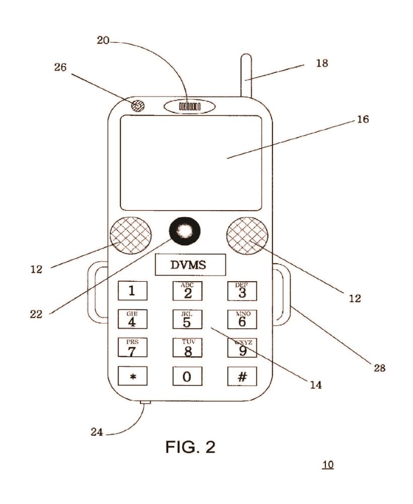
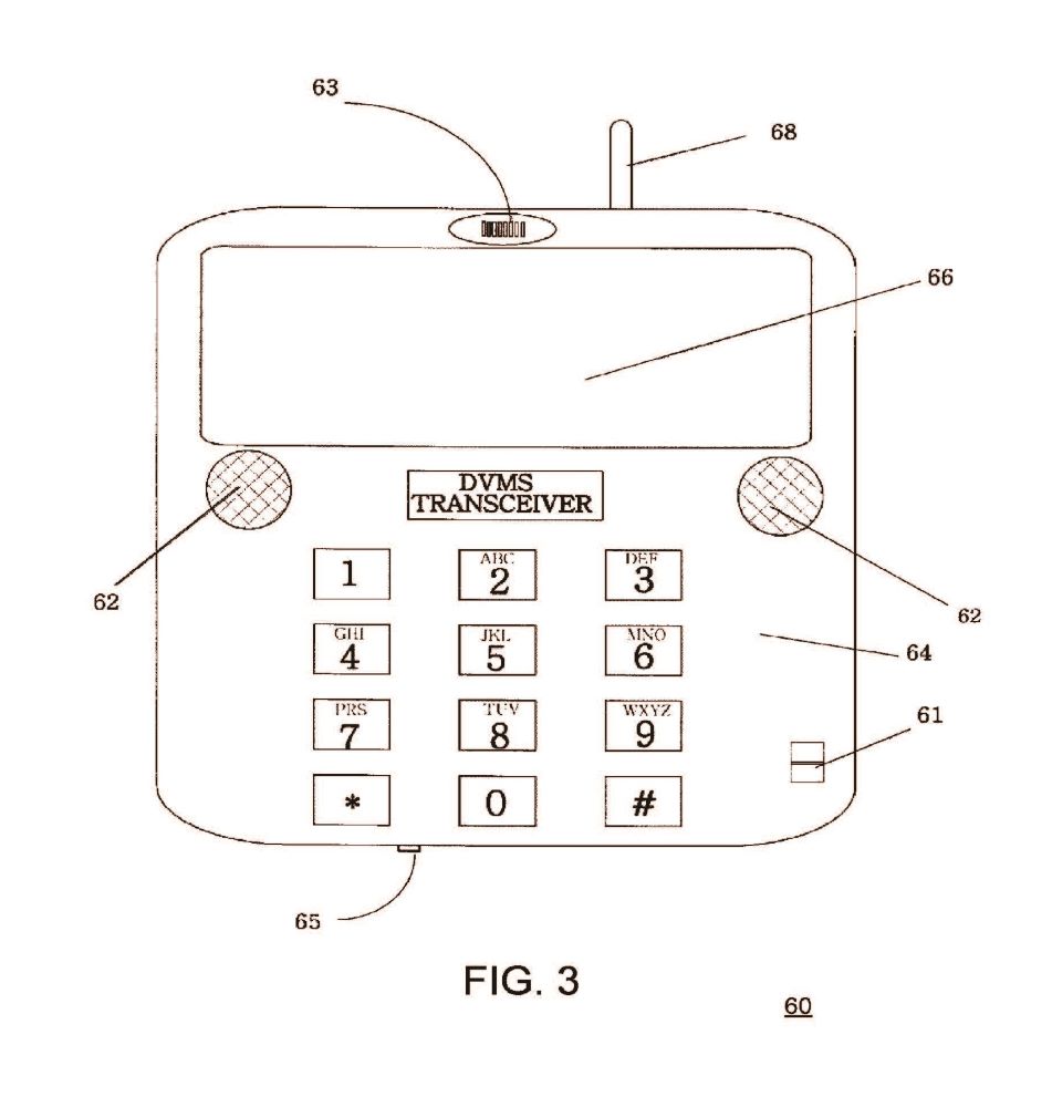
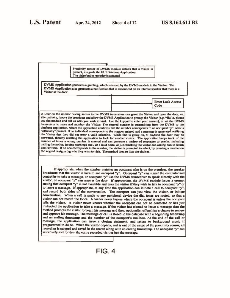
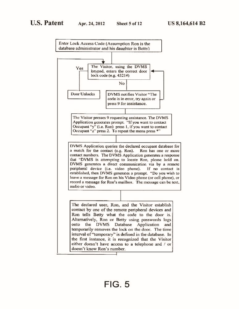
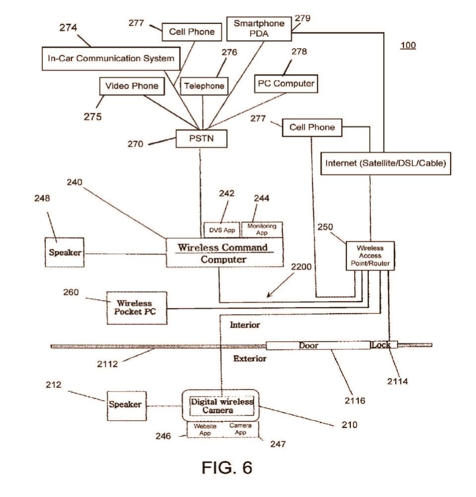

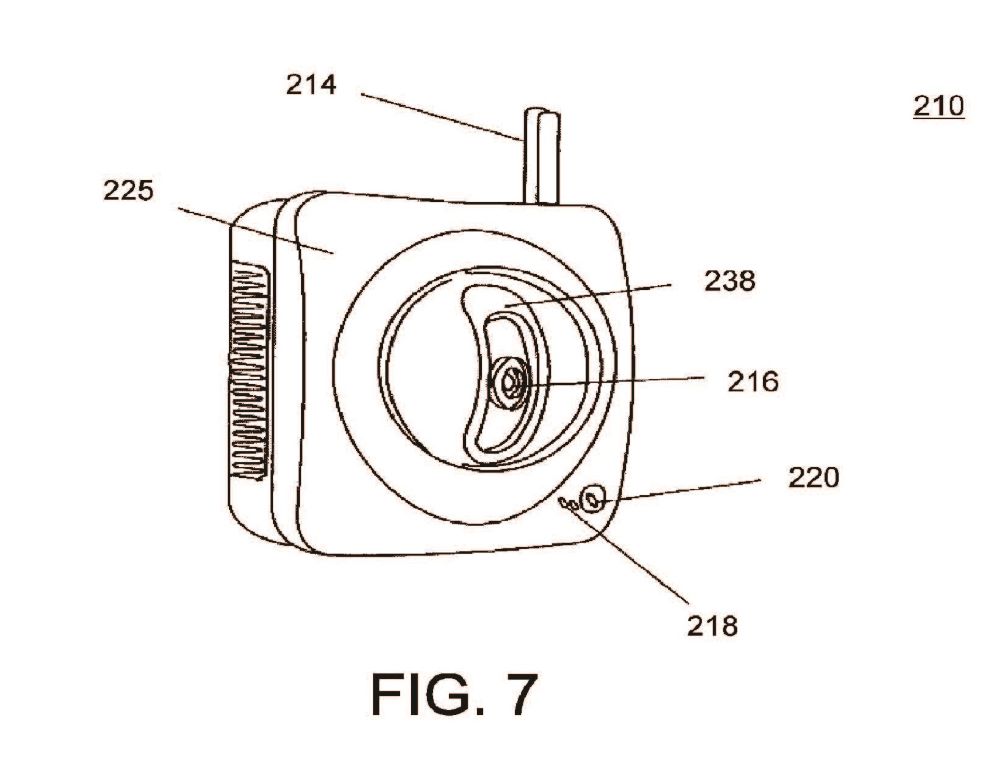
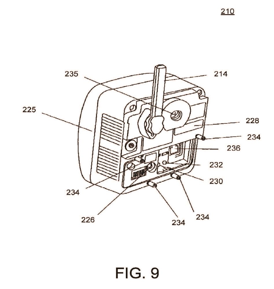
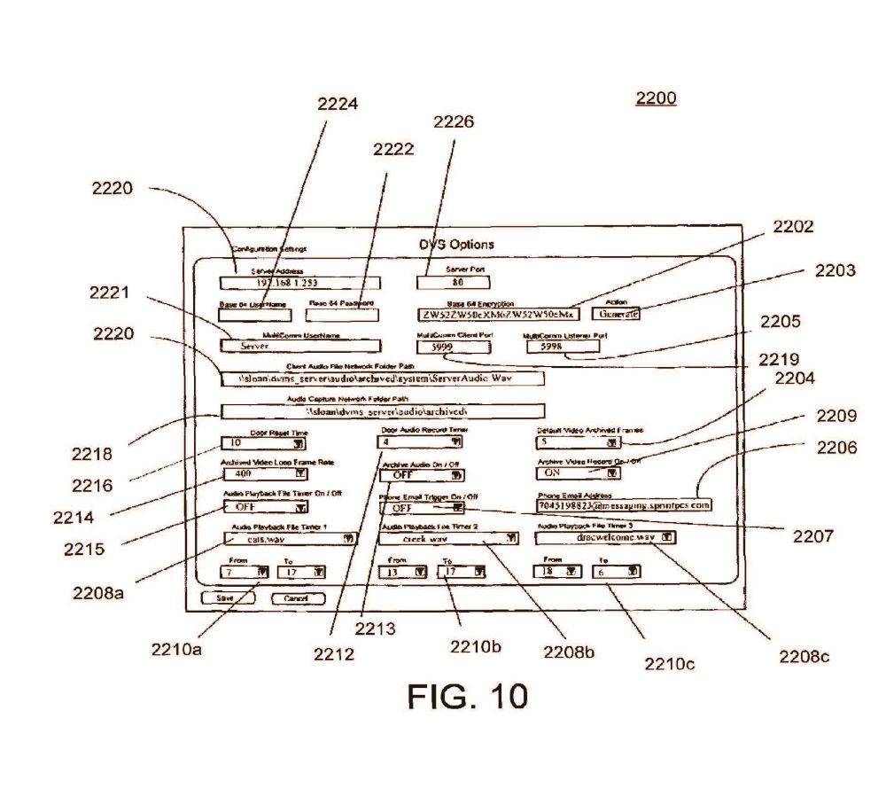
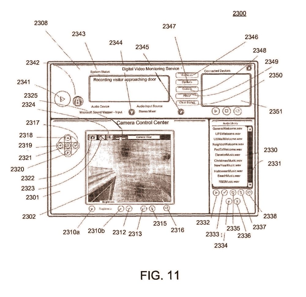
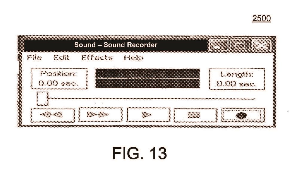
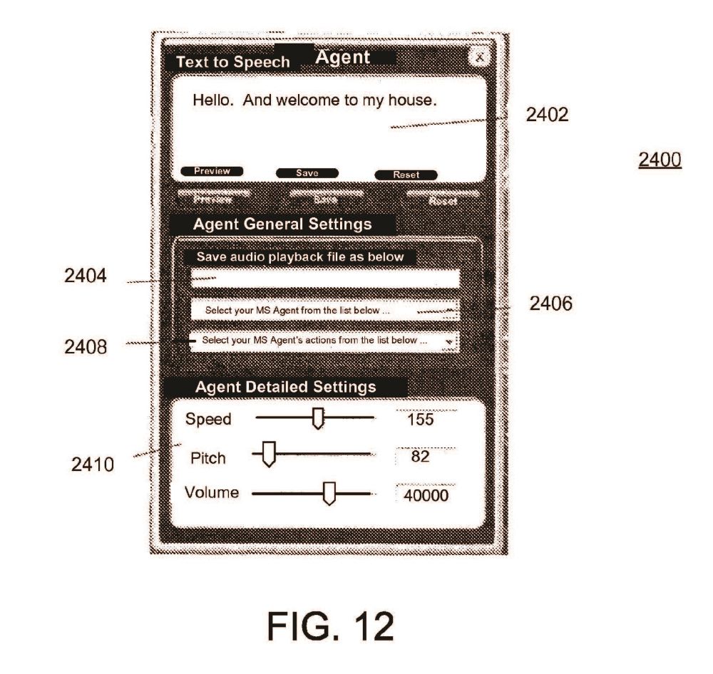

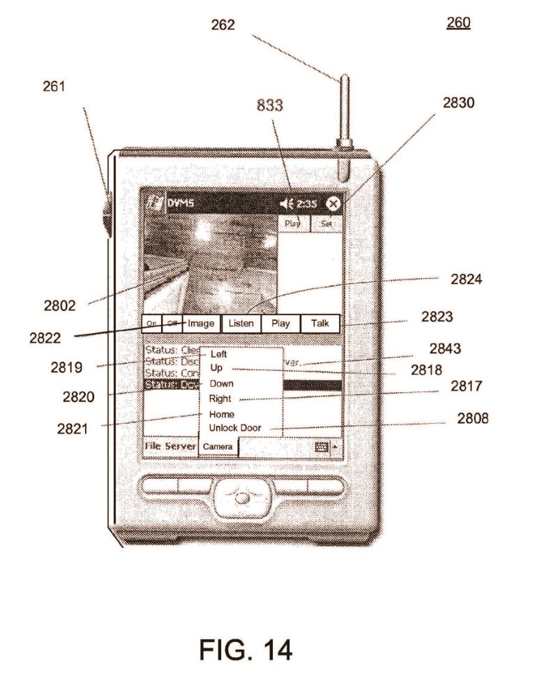
ABSTRACT
An audio-video communication system comprises a wireless exterior module located proximate an entrance, a computerized controller running a software application, and a remote peripheral device. The wireless exterior module includes a proximity sensor for detecting a person at the entrance, a video camera for recording an image of the person at the entrance, a microphone for recording the person at the entrance, a speaker for playing audio to the person at the entrance, a transmitter for communicating sounds and images of the person at the entrance, and a receiver for receiving communications at the wireless exterior module. The computerized controller is disposed in wireless electronic communication with the wireless exterior module via the transmitter and the receiver of the wireless exterior module. The remote peripheral device is configured to electronically communicate with the computerized controller for viewing an image from the video camera communicated from the wireless exterior module.
DESCRIPTION
I. CROSS REFERENCE TO RELATED APPLICATION
This application is a continuation patent application of, and claims the benefit under 35 U.S.C. §120 to, U.S. patent application Ser. No. 11/618,615, filed Dec. 29, 2006, published as U.S. Patent Appl. Publication No. 2007/0103548 A1, which patent application is a continuation-in-part patent application of, and claims the benefit under 35 U.S.C. §120 to, U.S. patent application Ser. No. 10/682,185, filed Oct. 9, 2003, published as U.S. Patent Application Publication No. 2005/0285934 A1, and now granted as U.S. Pat. No. 7,193,644, which patent application is a nonprovisional patent application of U.S. patent application Ser. No. 60/418,384, filed on Oct. 15, 2002, expired. Each of these patent applications, patent application publications, and patent is hereby incorporated herein by reference.
II. BACKGROUND OF THE INVENTION
There are numerous problems presently associated with receiving visitors at a home or office. When the resident of the home or occupant of the office (hereinafter generally referred to as either resident or occupant) is absent, there is often no message for the visitors, no means to leave an interactive message for the resident, and no means to ensure that unwanted access is not obtained. Moreover, answering the call of someone at a door of a dwelling can present certain security risks to an occupant therein. This situation can be especially inconvenient when, for example, a delivery or repair person arrives and the resident is not present. When the resident is present, on the other hand, there are also problems associated with receiving visitors. Some visitors may be unwelcome, for example, and it is often not evident that a visitor is a threat or an annoyance until after the door is open.
There are many types of systems for receiving a person by an occupant or resident and/or on the behalf of the occupant or resident. Such systems include those disclosed in each of: U.S. Pat. No. 5,148,468 titled “Door Answering System”, which issued Sep. 15, 1992 to Marrick et al; U.S. Pat. No. 5,303,300 titled “Security Door Phone Device,” which issued Apr. 12, 1994 to Eckstein; U.S. Pat. No. 5,406,618 titled “Voice Activated, Hands Free Telephone Answering Device,” which issued Apr. 11, 1995 to Knuth, et al.; and U.S. Pat. No. 5,657,380 titled “Interactive Door Answering and Messaging Device with Speech Synthesis,” which issued to Mozer on Aug. 12, 1997. Nevertheless, a need remains for further improvement in such a system.
III. SUMMARY OF THE INVENTIONThe invention includes many aspects and features. Moreover, while many aspects and features of the invention relate to, and are described in, the context of a system for receiving a person at an entrance, such as, an entrance to a home or business, the invention is not limited to use only in such context and may be used and has applicability in other contexts as well.
In one aspect of the invention, an audio-video communication system comprises a wireless exterior module located proximate an entrance, a computerized controller running a software application and a remote peripheral device. The wireless exterior module includes a proximity sensor for detecting a person at the entrance, a video camera for recording an image of the person at the entrance, a microphone for recording sound of the person at the entrance, a speaker for playing audio to the person at the entrance, a transmitter for communicating sounds and images of the person at the entrance, and a receiver for receiving communications at the wireless exterior module. The computerized controller is disposed in wireless electronic communication with the wireless exterior module via the transmitter and the receiver of the wireless exterior module. The computerized controller is configured to control recording of communications with the wireless exterior module and playback of such recording, and the software application includes a graphic user interface that enables a user to view images from the video camera communicated from the wireless exterior module. The remote peripheral device is configured to electronically communicate with the computerized controller for viewing an image from the video camera communicated from the wireless exterior module.
In a feature of the first aspect, the audio-video communication system further comprises a second wireless exterior module located proximate an entrance, with the second wireless exterior module having a proximity sensor for detecting a person at the entrance, a video camera for recording an image of the person at the entrance, a microphone for recording sound of the person at the entrance, a speaker for playing audio to the person at the entrance, a transmitter for communicating sounds and images of the person at the entrance, and a receiver for receiving communications at the wireless exterior module. The computerized controller running the software application is further disposed in wireless electronic communication with the second wireless exterior module via the transmitter and the receiver of the second wireless exterior module.
In another feature of this aspect, the remote peripheral device is configured to remotely actuate the camera of the wireless exterior module. In an additional feature, the graphic user interface enables a user to view streaming video with the remote peripheral device. In yet another feature, the remote peripheral device comprises a cell phone. In still yet another feature, the remote peripheral device comprises a video phone. In further features, the remote peripheral device comprises a computer and a personal digital assistant.
In an additional feature, the entrance comprises an entrance of a business. In another additional feature, the entrance comprises an entrance of a residence. In a further feature, the wireless exterior module includes a display screen. In still a further feature, the wireless exterior module includes a keypad comprising a touch screen or a keyboard. In yet a further feature, the wireless exterior module is portable and includes a locking mechanism and an electrical receptacle for quickly attaching to a source of electricity.
In another feature, the wireless exterior module has a portable energy source and is secured in a holster. In yet another feature, the computerized controller comprises a personal computer. In still yet another feature, the computerized controller is disposed in electronic communication with a public switching telephone network (PSTN).
In a further feature, the computerized controller is disposed in electronic communication with the Internet. In an additional feature, the audio-video communication system further comprises an electronically actuated lock that is configured to be unlocked by the computerized controller. In another feature, the system further comprises a voice recognition system.
In still a further feature, a transceiver includes the transmitter for communicating sounds and images of the person at the entrance and the receiver for receiving communications at the wireless exterior module. In yet another feature, the computerized controller includes an image recognition module for identifying at least one of faces, eyes, and fingerprints.
In a second aspect of the invention, a method for two-way audio-video communications between a first person at an entrance and a second person comprises the steps of (a) detecting, with a proximity sensor located proximate an entrance, the presence of a first person at the entrance; and (b) providing real time audio-video communications between the first person at the entrance and a second person using a wireless handheld device. Step (b) is done by (i) transmitting, to the wireless handheld device of the second person, video of the first person at the entrance recorded using a camera located proximate the entrance, (ii) transmitting, to the wireless handheld device of the second person, audio of the first person at the entrance recorded using a microphone located proximate the entrance, and (iii) transmitting, to a speaker located proximate the entrance for playing to the first person at the entrance, audio of the second person recorded using the wireless handheld device.
In a feature of this aspect, the transmitting includes wireless communications between both the camera and microphone located proximate the entrance and a computerized controller running a software application including a graphic user interface by which the audio-video communications between the first person and the second person are established. In another feature, the method further comprises the step of playing a recorded greeting to the first person at the entrance upon the detection of the first person at the entrance with the proximity sensor. With regard to this feature, the method further comprises determining, by a user with a remote peripheral device, the recorded greeting that is played through a graphical user interface. With further regard to this feature, the recorded greeting is selected by the user from a plurality of recorded greetings. It accordance with this feature, the recorded greetings are seasonal greetings. It is preferred that the recorded greeting includes audio and video.
In an additional feature, the method further comprises the step of posting, by the user from a remote peripheral device, a video greeting for presentation to a first person at the entrance. In further features, the wireless handheld device comprises a cell phone, a video phone, and a personal digital assistant.
In yet another feature, the entrance comprises an entrance of a business. In still a further feature, the entrance comprises an entrance of a residence. In another feature, the method further comprises the step of saving a recording of the two-way audio-communications in a database for later playback. In yet another feature, the method further comprises transmitting, to a video display located proximate the entrance for presentation to the first person at the entrance, video of the second person recorded using the wireless handheld device.
In an additional feature, the transmitting includes communications over the Internet. In further features, the transmitting includes communications over a cellular network and over a satellite network. In yet another feature, the method further comprises remotely actuating the camera located proximate the entrance using the wireless handheld device. In still further features, the step of remotely actuating the camera includes zooming an image of the first person at the entrance and remotely moving the camera to change the view of the camera.
In a third aspect of the invention, a method for receiving a person at an entrance comprises the steps of (a) detecting, with a proximity sensor located proximate an entrance, the presence of a person at the entrance; (b) transmitting, to a computerized controller running a software application, video of the person at the entrance recorded using a camera located proximate the entrance; and (c) providing, with the application software running at the computerized controller, a graphic user interface to a remote peripheral device by which a user of the remote peripheral device may view the video of the person at the entrance.
In a feature of this aspect, the method further comprises the step of saving, in accordance with the application software running at the computerized controller, the video of the person at the entrance in a database in association with a timestamp. In other features, the video is viewed using the remote peripheral device in real-time, viewed using the remote peripheral device after the person at the entrance has left, and is streamed to the remote peripheral device.
In an additional feature, the method further comprises the step of transmitting, to the computerized controller running the software application, audio of the person at the entrance recorded using a microphone located proximate the entrance; wherein the graphic user interface provided to the remote peripheral device further enables a user of the remote peripheral device to hear the audio of the person at the entrance. In another feature, the method further comprises the step of playing a recorded greeting to the person at the entrance upon the detection of the person at the entrance with the proximity sensor.
In another feature, the method further comprises determining, by a user with the remote peripheral device, the recorded greeting that is played through a graphical user interface. With regard to this feature, the recorded greeting may be selected by the user from a plurality of recorded greetings, the recorded greetings may be seasonal greetings, and the recorded greeting may include audio and video.
In yet another feature, the method further comprises the step of posting, by the user from the remote peripheral device, a video greeting for presentation to a person at the entrance. In other features, the remote peripheral device comprises a cell phone, a video phone, a computer, and a personal digital assistant. In still other features, the entrance comprises an entrance of a business and an entrance of a residence.
In still another feature, the method further comprises remotely actuating the camera located proximate the entrance using the remote peripheral device. In further features, the step of remotely actuating the camera includes zooming an image of the person at the entrance and remotely moving the camera to change the view of the camera.
In addition to the aforementioned aspects and features of the present invention, it should be noted that the present invention further encompasses the various possible combinations of such aspects and features.
IV. BRIEF DESCRIPTION OF THE DRAWINGS
One or more preferred embodiments of the invention now will be described in detail with reference to the accompanying drawings.
FIG. 1 is a schematic diagram of a system in accordance with a preferred embodiment of the invention.
FIG. 2 is a planar view of the font of a DVMS module of the system of FIG. 1
FIG. 3 is a planar view of the front of a DVMS transceiver of the system of FIG. 1.
FIG. 4 is a block diagram overview of a method in accordance with a preferred embodiment of the invention.
FIG. 5 a block diagram extension of the method of FIG. 4.
FIG. 6 is a schematic diagram of a system in accordance with another preferred embodiment of the invention.
FIG. 7 is a perspective view of the front of a wireless network camera of the system of FIG. 6.
FIG. 8 is a side view of the wireless network camera of FIG. 7.
FIG. 9 is a perspective view of the rear of the wireless network camera of FIG. 7.
FIG. 10 is a representative screen view of a wireless command center of the system of FIG. 6, wherein various parameter settings for configuring, e.g., the audio, video, server, and cell phone options are illustrated.
FIG. 11 is a screen view of the normal operating mode interface of the wireless command center of FIG. 10, wherein a user is able to dynamically control a wireless network camera, view video images generated by the wireless network camera, listen and send both pre-canned and live audio files, and review archived system events.
FIG. 12 is a dialog box screen view of the text-to-voice synthesizer module of the wireless command center of FIG. 10.
FIG. 13 is a dialog box screen view of the recorded voice synthesizer module of the wireless command center of FIG. 10.
FIG. 14 is a planar view of the front of a wireless pocket PC that is connected to a wireless network, wherein a user of the wireless pocket PC is able to dynamically control the wireless network camera, view video images generated by the wireless network camera, listen and send both pre-canned and live audio files, and review archived system events in the system of FIG. 6.
V. DETAILED DESCRIPTION
As a preliminary matter, it will readily be understood by one having ordinary skill in the relevant art (“Ordinary Artisan”) that the present invention has broad utility and application. Furthermore, any embodiment discussed and identified as being “preferred” is considered to be part of a best mode contemplated for carrying out the present invention. Other embodiments also may be discussed for additional illustrative purposes in providing a full and enabling disclosure of the present invention. Moreover, many embodiments, such as adaptations, variations, modifications, and equivalent arrangements, will be implicitly disclosed by the embodiments described herein and fall within the scope of the present invention.
Accordingly, while the present invention is described herein in detail in relation to one or more embodiments, it is to be understood that this disclosure is illustrative and exemplary of the present invention, and is made merely for the purposes of providing a full and enabling disclosure of the present invention. The detailed disclosure herein of one or more embodiments is not intended, nor is to be construed, to limit the scope of patent protection afforded the present invention, which scope is to be defined by the claims and the equivalents thereof. It is not intended that the scope of patent protection afforded the present invention be defined by reading into any claim a limitation found herein that does not explicitly appear in the claim 1tself.
Thus, for example, any sequence(s) and/or temporal order of steps of various processes or methods that are described herein are illustrative and not restrictive. Accordingly, it should be understood that, although steps of various processes or methods may be shown and described as being in a sequence or temporal order, the steps of any such processes or methods are not limited to being carried out in any particular sequence or order, absent an indication otherwise. Indeed, the steps in such processes or methods generally may be carried out in various different sequences and orders while still falling within the scope of the present invention. Accordingly, it is intended that the scope of patent protection afforded the present invention is to be defined by the appended claims rather than the description set forth herein.
Additionally, it is important to note that each term used herein refers to that which the Ordinary Artisan would understand such term to mean based on the contextual use of such term herein. To the extent that the meaning of a term used herein—as understood by the Ordinary Artisan based on the contextual use of such term—differs in any way from any particular dictionary definition of such term, it is intended that the meaning of the term as understood by the Ordinary Artisan should prevail.
Furthermore, it is important to note that, as used herein, “a” and “an” each generally denotes “at least one,” but does not exclude a plurality unless the contextual use dictates otherwise. Thus, reference to “a picnic basket having an apple” describes “a picnic basket having at least one apple” as well as “a picnic basket having apples.” In contrast, reference to “a picnic basket having a single apple” describes “a picnic basket having only one apple.”
When used herein to join a list of items, “or” denotes “at least one of the items,” but does not exclude a plurality of items of the list. Thus, reference to “a picnic basket having cheese or crackers” describes “a picnic basket having cheese without crackers”, “a picnic basket having crackers without cheese”, and “a picnic basket having both cheese and crackers.” Finally, when used herein to join a list of items, “and” denotes “all of the items of the list.” Thus, reference to “a picnic basket having cheese and crackers” describes “a picnic basket having cheese, wherein the picnic basket further has crackers,” as well as describes “a picnic basket having crackers, wherein the picnic basket further has cheese.”
Referring now to the drawings, one or more preferred embodiments of the present invention are next described. The following description of one or more preferred embodiments is merely exemplary in nature and is in no way intended to limit the invention, its applications, or uses.
The System of FIG. 1FIG. 1 is a schematic diagram of a system 100 in accordance with a preferred embodiment of the invention. For purposes of providing an enabling description, the system 100 is described in the context of a door answering system for receiving a person at a home or office and is capable of controlling access to the home or office. In FIG. 1, the exterior of the home or office is differentiated from the interior by demarcation line 115, which represents a wall or other similar structure. The wall 115 includes an entrance in the form of a door 114 and an electronically actuated lock 116 for selectively locking and unlocking the door 114.
A computerized controller in the form of a personal computer 80 is disposed in the interior and is configured to selectively actuate the lock 116. The personal computer 80 preferably includes a DVD-R/W 84, a CD-ROM R/W 92, and a hard drive 86. One or more of these components 84,92,86 of the personal computer 80 preferably are utilized for recording video and audio communications that are transmitted to and from the DVMS module 10 (described in further detail below) and for playing video and audio communications that are stored via the personal computer 80.
The personal computer 80 also may include a voice generator 90 for use in generating prompts, which either exists as pre-recorded messages or are generated by a voice synthesizer. Each of these components 84,92,86,90 of the personal computer 80 may be separately disposed from the personal computer and connected, for example, by a switch 88, or may form part of the personal computer 80 and be disposed in electronic communication with a bus of the personal computer 80 within the housing thereof.
A speaker 44 is disposed in electronic communication with the personal computer 80. The speaker 44 is not shown as being wireless, but could be. Moreover, one speaker 44 is shown, but additional speakers could be used in the system 100. Furthermore, speaker 44 in FIG. 1 is represented as being separate from the personal computer 80, however, the speaker 44 could alternatively form part of the personal computer 80.
The personal computer 80 preferably is disposed in electronic communication with the Internet. The connection with the Internet preferably is accomplished by a broadband connection such as a connection 81 provided by a satellite modem, a DSL model, or a cable modem, or any combination thereof.
The personal computer 80 also preferably is connected to a public switching telephone network (PSTN) 70, which enables communication by and with the personal computer 80 via standard telephone lines.
The personal computer 80 preferably has a battery backup as well as a means for detecting a loss in electrical power such that, when electrical power is lost the battery backup will provide sufficient operating time for the personal computer 80 to notify someone responsible for the maintenance of the system that there has been a loss of electricity. Notification of the loss of electricity can be important, since the loss of electrical power can be an indication of a burglary. Additionally, if there is no electricity, then appliances, such as refrigerators, air conditioners, and heaters, cannot function and significant damage can results if the electrical failure goes undetected for a substantial period of time.
The personal computer 80 runs a software application that includes a DVMS Database Application 82 and graphic user interfaces (GUIs). The personal computer 80, in accordance with the software application, controls communication in the system 100, coordinates multiple communication devices in the system 100, and is used to define responses to prompts and events in the system 100. The DVMS Database Application 82 and its uses are described in greater detail below.
The system 100 further includes a wireless router 42 located in the interior. The wireless router 42 in FIG. 1 is represented as being separate from the personal computer 80, however, the wireless router 42 could alternatively form part of the personal computer 80. The wireless router 42 is used to establish a wireless network and is disposed in electronic communication with the personal computer 80.
The system 100 also includes a DVMS module 10 located on the exterior of the home or office proximate the door 114. The DVMS module 10 is configured for use in the exterior of the home or office, which may include outdoor use in external residential or commercial locations. The DVMS module 10 is disposed in wireless communication with the wireless network, including the personal computer 80, via the wireless router 42.
With reference to FIG. 2, the DVMS module 10 preferably includes: a video camera 22; speakers 12; a proximity sensor 26; a microphone 20; an LCD display 16; a quick connect electrical receptacle 24; and a radiofrequency receiver/transmitter represented by antenna 18. The proximity sensor 26 activates the camera 22 upon detection of movement, which in turn relays an image or streaming video to the personal computer 80 where it is saved by the personal computer 80 in a database in association with a timestamp. Operation of the system is described in further detail below.
The DVMS module 10 optionally includes a small portable energy source, such as a battery that is rechargeable via the quick connect electrical receptacle 24, for portable use as well as for use in the event of a power failure.
The LCD display 16 screen preferably is a low energy screen reducing energy consumption. The LCD display 16 preferably comprises a touch screen and can be used to send and receive text similar to a keypad. Alternatively, or in addition thereto, the DVMS module 10 includes a keypad 14. In either case, the DVMS module 10 enables text messaging by a person at the exterior, which in turn enables a private non-audible conversation to be had and eliminates risks of eavesdropping by a passerby.
The DVMS module 10 also includes a locking mechanism 28 for receipt in a mounting holster (not shown). The locking mechanism 28 enables the DVMS module 10 to be installed securely wherever holstered, or to be moved to some other remote location, as desired. The DVMS module 10 thus is portable, much like a cell phone, and can be securely mounted and quickly connected to an electrical source.
It is anticipated that there could be multiple entrances to the home or office and, similarly, multiple DVMS modules similar to DVMS module 10 of FIG. 2 could be utilized, each disposed in wireless communication with the wireless network via the wireless router 42.
The system optional includes one or more DVMS transceivers 60. The DVMS transceivers 60 is configured for use in the interior of the home or office. As illustrated in FIG. 1, a DVMS transceivers 60 may be disposed in wireless communication with the wireless network, including the personal computer 80, and the DVMS module 10, via the wireless router 42. Additionally or alternatively, a DVMS transceivers 60 may be configured to wirelessly communicate directly with the DVMS module 10, thus bypassing communications through the wireless router 42.
With reference to FIG. 3, each DVMS transceiver 60 is portable and, like the DVMS module 10, the DVMS transceiver 60 communicates by short-range radiofrequency transmissions. The DVMS transceiver 60 includes: speakers 62; a microphone 63; an LCD display 66; a quick connect electrical receptacle 65; and a radiofrequency receiver/transmitter represented by antenna 68. The DVMS transceiver 60 optionally includes a small portable energy source, such as a battery that is rechargeable via the quick connect electrical receptacle 65, for portable use as well as for use in the event of a power failure. The DVMS transceiver 60 further includes a mute switch 61, which cuts-off the microphone 63, thus assuring a user of the DVMS transceiver 60 that a visitor can be monitored using the DVMS transceiver 60 without inadvertently sending an audible signal from the user.
The LCD display 66 screen preferably is a low energy screen reducing energy consumption. The LCD display 66 preferably comprises a touch screen and can be used is used to send and receive text similar to a keypad. Alternatively, or in addition thereto, the DVMS transceiver 60 includes a keypad 64. In either case, the DVMS module 60 enables text messaging by a user of the DVMS transceiver 60 with a person at the exterior using the DVMS module 10, which in turn enables a private non-audible conversation to be had and eliminates risks of eavesdropping by a passerby.
The system 100 further includes one or more remote peripheral devices. Such devices generally include video phones 72; in-car communication systems such as the well known ONSTAR system 74 currently found in GM cars; telephones 76; cell phones 77; personal computers 78; smartphones/personal digital assistants (PDAs) 79; and other similar communication devices. Each remote peripheral device is configured for electronic communication with the personal computer 80 via at least the PSTN connection 70 or the broadband connection 81.
As mentioned above, the personal computer 80 runs a software application that includes a DVMS Database Application 82 and graphic user interfaces (GUIs). The software application is configured and maintained by an administrator, who defines users thereof. The users in the system 100 are referred to as “occupants” reflecting their relation to the home or office.
Preferably, the occupants have various levels of access to the software application, depending on the privileges set by the administrator. The administrator may also set a level of security under which the system is to operate, particularly with respect to connections made using remote peripheral devices.
Other examples of configuration settings of the software application that are determined by the administrator include: aliases for a declared occupant such as, e.g., “Daddy” or “Momma”; passwords to access the software application; access codes to actuate the electronic lock controlled by the computerized controller; a number or other identifier that corresponds to an occupant's name; and at least one telephone number by which an occupant can be reached. The administrator also preferably defines a preferred hierarchy of storage of audio and video data, the location and number of backup devices, and whether replications of the database are to be kept.
Additionally, when setting up the software application, the administrator chooses, inter alia: a prompt for greeting a visitor; chooses an announcement that is to be given over a speaker within the interior when a visitor arrives; a prompt for requesting information from a visitor; a request instructing a visitor as to their choices in leaving a message or contacting a declared user; and the action that is to be performed by the computerized controller based on the input by the visitor.
The administrator also tailors the security/premise monitoring response by, inter alia: designating telephone numbers that the computerized controller calls when, for example, there is a loss of power; and designating telephone emergency numbers (e.g., telephone numbers for the police, the fire department, relatives, private security companies) that the computerized controller calls when an emergency is detected. The computerized controller also conducts self checks to confirm that all the components of the system are operational and keeps a log of the self checks, and the computerized controller preferably calls one or more designated numbers when a self check indicates a failure or otherwise improper operation.
The software application also can be configured to play background music or videos at different times of the year and/or different times of the day to reflect seasonal holidays, birthdays, and events. For instance, on Halloween the administrator may wish to have scary music and howls issuing from the DVMS module for receiving a person at that time. Furthermore, utilizing the computerized controller, the administrator can choose to use default prompts for interacting with a visitor or create customized prompts.
As hardware is added, such as the number of the DVMS modules and DVMS transceivers, the administrator can update both the network to include the additional devices and the computerized controller to accommodate the additional devices.
The software application also is configured to send voice, text, and video messages via email. The administrator can further set up redundant subsystems of the system 100.
The system 100, in use, enables secure and effective monitoring and interacting with a visitor at a residence or business, including, inter alia: the detection of the presence of a visitor at the exterior of the home or office via the proximity sensor 26, the interactive communication with the visitor, whether an occupant is present or absent from the home or office, the enablement of automated entry into the home or office by the visitor, and personalization of the process of receiving a visitor.
An exemplary method of use in the system 100 includes greeting and communicating with visitors of a business or residence. In accordance with the method, the presence of a visitor is detected via the proximity sensor 26 of the DVMS module 10, where the DVMS module 10 is mounted at or near an entrance to the business or residence. Upon the detection of the visitor by the proximity sensor 26, a message is communicated to the personal computer 80 from the DVMS module 10 indicating the detection of a visitor at the entrance. A recording is actuated by the personal computer 80, and the recording is stored in a computer-readable medium such as a database along with a beginning time-stamp. The arrival of a visitor is broadcast over a speaker within the home or office, such as speaker 44. An occupant can view the visitor on a display on the DVMS transceiver 60 or on a display of the personal computer 80, and the occupant can initiate a conversation at any time. The DVMS module 10 issues a greeting to the visitor and instructs the visitor to select a number from the keypad 14 of the DVMS module 10 in order to designate the occupant being visited. The entered number is communicated from the DVMS module 10 to the personal computer 80, where the software application confirms that the number corresponds to an occupant “y” who is “officially” present. An error message is generated if no individual corresponds to the number entered by the visitor. If no individual corresponds to the number entered by the visitor, then the visitor is prompted to select and press another number on the keypad 14 again designating the occupant being visited. The method then lists the choices again.
While this is going on, the door may be answered at any time, thereby resetting the software application to look for another visitor. The software application keeps track of the number of times a wrong number is entered and can generate a variety of responses to pranks, including calling the police, issuing warnings and/or a loud noise, or just thanking the visitor and asking him to return another time.
If appropriate, when the number designated by the visitor matches an occupant who is officially on the home or office, the speaker broadcasts that the visitor is here to see occupant “y”. Occupant “y” can signal the personal computer 80 to take a message, or occupant “y” may choose to use the DVMS transceiver 60 to speak directly with the visitor, or occupant “y” can answer the door.
If appropriate, the DVMS module 10 issues a prompt stating that occupant “y” is not available and asks the visitor if they wish to speak to occupant “y” or to leave a message.
If appropriate, at any time the software application can initiate a call to occupant “y” via a remote peripheral device for communication between occupant “y” and the visitor, and the software application can record both sides of the conversation between occupant “y” and the visitor. The occupant can view the visitor or initiate a conversation, as the occupant desires. A visitor never knows where the occupant is, unless the occupant tells the visitor of the occupant's location. A visitor also never knows if the occupant can be contacted, or if the occupant has just instructed the application to take a message. Using the method the conversation or messages can be relayed to the selected occupant without the visitor ever knowing where the location of the occupant. Only the occupant can disclose such location to the visitor as desired.
If the visitor elects to leave a message, then the method prompts the visitor to begin his message and then, optionally, offers him a chance to review and approve his message. The message or call is stored in computer readable medium, such as database, by the personal computer 80 in association with a beginning timestamp and an ending timestamp along with the occupant's mailbox number. At the end of the call or message, the software application can issue a closing statement and return to background music, if programmed to do so.
When the visitor departs, and is out of the range of the proximity sensor 26, all recording is stopped and saved in the database record, along with an ending timestamp. The occupant “y” can selectively sort to view the entire recorded visit, or just the message.
If the proximity sensor 26 indicates that there is another visitor, the method cycles back to the greeting step.
If the system has an electronically actuated lock, then the method also may include the steps of checking the number entered by the visitor to determine if it is a valid access code. The electronically actuated lock may be unlocked by entering an access code either at the DVMS module 10 or remotely therefrom. If the number is valid, then the lock is actuated, and if the number is not valid, then a prompt is made requested that the code be re-entered. Optionally, the prompt may further request a number be entered that corresponds to one of the occupants if assistance is needed and, if an occupant is selected, then calling the selected occupant. The method also may include tracking how many times the wrong code is entered; checking if the maximum allowed number of wrong entries have been made; and, when the maximum number of wrong entries is reached, either automatically calling a designated party and/or removing access privileges.
An occupant preferably has the option of remotely entering the access code, thereby actuating the electronically actuated lock, or instructing the GUI database application to go to a new high security level, wherein the lock cannot be accessed and notifying the visitor that the access code is not operational.
In the method, upon the entering of a valid access code assigned to a declared occupant, the software application optionally notifies the administrator or his designated representative that the declared occupant has now entered the home or office. The administrator would know who the individual should be. The administrator thus can confirm, by remotely viewing the recorded video, that the actual person who entered the access code is the declared occupant, and/or make a follow-up telephone call to the home or office. The system 100 also provides the options of allowing the visitor to converse with the occupant, leaving a message, or calling a remote peripheral device for communication with the occupant when he is either not present or is unavailable. The entrance is recorded and time stamped for sorting or viewing either in real time or at a later date.
The system 100 further enables the administrator or a declared occupant to, at any time, to turn on a camera and view images, access the recorded the video images, or post a video image from a remote peripheral device to computerized controller including associated components.
The system 100 preferably is inherently extensible in both form and function and is designed so that the system can be expanded to include multiple peripheral devices, both in direct and indirect communication with the computerized controller. Due to the use of the computerized controller and its interconnectivity, the disclosed system 100 can be configured to accommodate communications having a range of complexity.
As will be apparent from the foregoing, the system 100 provides an audio-video communication and answering system that provides real time communication between an exterior of a business or residence and an interior of the business or residence as well as a location remotely located to the business or residence.
As will be apparent from the foregoing, the system 100 provides an audio-video communication and answering system that provides real time communication between two or more rooms at a home or office and a remote location.
As will be apparent from the foregoing, the system 100 provides an audio-video communication and answering system that provides the ability to leave messages at a centralized location from a local or remote location.
In addition to the foregoing description of a method, FIG. 4 shows a block diagram illustrating an example of the use of a system of the invention as a door answering and messaging system at a residence. Furthermore, FIG. 5 shows a block diagram illustrating an example of the use of a system of the invention as a door answering and messaging system at a residence, wherein the system includes an electronically actuated lock. In the example, an occupant is attempting to gain access to the home or office.
As will now be apparent, systems in accordance with the invention achieve one or more of the foregoing benefits and features yet remain intuitive and easy to use.
In addition to the foregoing, it further is anticipated that, in certain deployments of the invention, voice recognition would be useful, particularly when the system enables access to a home or office. Voice recognition adds another layer of security, and can be used to facilitate those individuals who are unable to press a keypad. Similarly, image recognition of faces, eyes and fingerprints can also be included in the system for authentication, security, and access. The software application thus alternatively utilizes voice recognition and/or image recognition.
Furthermore, while no camera is shown located within the home or office, any number of cameras could be utilized on the interior.
It will also be appreciated that a business may be a tenant located within a building shared by other businesses. A DVMS module for the business thus would be utilized on the exterior of the business, i.e., at the “front door” of the business, which would be located within the interior of the common building.
In variations of systems of the invention, it should further be noted that one or more devices having the functionality of DVMS modules could be utilized in the interior for securing entrance to a room or group of rooms.
The System of FIG. 6
FIG. 6 is a schematic diagram of a system 2100 in accordance with another preferred embodiment of the invention. The system 2100 includes: a local area network 2200; a wireless digital camera 210; and a computerized controller in the form of a personal computer 240 (identified as the “Wireless Command Computer” in FIG. 6). The lines indicate communications between member devices and components of the system 2100 and such communications may be wired, wireless, or a combination of both wired and wireless. For purposes of providing an enabling description, the system 2100 is described in the context of a door answering system for receiving a person at a home or office and is capable of controlling access to the home or office. In FIG. 6, the exterior of the home or office is differentiated from the interior by a wall 2112 or other similar structure. The wall 2112 includes an entrance in the form of a door 2116 and an electronically actuated lock 2114 for selectively locking and unlocking the door 2116.
The personal computer 240 is disposed in the interior and is configured to selectively actuate the lock 2114. The personal computer 240 includes one or more components utilized for recording video and audio communications and for playing video and audio communications. The personal computer 240 also may include a voice generator for use in generating prompts, which either exists as pre-recorded messages or is generated by a voice synthesizer. Each of these components of the personal computer 240 may be separately disposed from the personal computer and connected, for example, by a switch, or may form part of the personal computer 240 and be disposed in electronic communication with a bus of the personal computer 240 within the housing thereof. A speaker 248 is disposed in electronic communication with the personal computer 240. Moreover, one speaker 248 is shown, but additional speakers could be used in the system 2100. Furthermore, speaker 248 in FIG. 6 is represented as being separate from the personal computer 240, however, the speaker 248 could alternatively form part of the personal computer 240.
The personal computer 240 preferably is disposed in electronic communication with the Internet. The connection with the Internet preferably is provided by a broadband connection through, for example, a wireless router 250. Such broadband connection may be accomplished by a satellite modem, a DSL model, or a cable modem, or any combination thereof. The personal computer 240 also preferably is connected to a public switching telephone network (PSTN) 70, which enables communication by and with the personal computer 240 via standard telephone lines.
The personal computer 240 preferably has a battery backup as well as a means for detecting a loss in electrical power such that, when electrical power is lost the battery backup will provide sufficient operating time for the personal computer 240 to notify someone responsible for the maintenance of the system that there has been a loss of electricity. Notification of the loss of electricity can be important, since the loss of electrical power can be an indication of a burglary. Additionally, if there is no electricity, then appliances, such as refrigerators, air conditioners, and heaters, cannot function and significant damage can results if the electrical failure goes undetected for a substantial period of time.
With regard to the wireless router 250, it is represented as being separate from the personal computer 240, however, the wireless router 42 could alternatively form part of the personal computer 240. The wireless router 42 is used, inter alia, to establish a wireless network and is disposed in electronic communication with the personal computer 240. The router 250 is WiFi compliant, and operates using a standardized protocol such as, for example, 802.11(b) and/or 802.11(g).
The wireless router 250 facilitates two-way communication over the local area network 2200 among the member devices and components of the wireless network 2200. Furthermore, the wireless router 250 preferably is disposed in electronic communication with the Internet and facilitates two-way communication between the member devices and components of the wireless network 2200 and remote devices communicating over the Internet. Such remote devices generally include video phones 275; in-car communication systems, such as the well known ONSTAR system 274 currently found in GM cars; telephones 276; cell phones 277; personal computers 278; smartphones/personal digital assistants (PDAs) 279; and other similar communication devices. Each remote device preferably is configured for electronic communication with one or more of the member devices and components of the wireless network 2200 via at least the PSTN connection 270 or a broadband Internet connection. Additionally, a remote device may be configured to communicate with one or more of the member devices and components of the wireless network 2200 via direct wireless communications with the wireless router 250 when such remote device is within communications range of the wireless router 250. Such direct wireless communications with the wireless router 250 is illustrated with the cell phone 277 in FIG. 6.
The wireless command computer includes a digital video system application (“DVS App”) 242 and a monitoring application 244. The DVS App 242 provides a set of customizable operating parameters for the wireless digital camera 210. The set of digital video operating parameters may include parameters selected from the group of: a default camera position; a number of frames per second; sensitivity and threshold of a motion sensor; length of a session; frequency of motion detection; and sensitivity and threshold of the motion detector. These parameters are conveyed to the camera operation application, discussed in further detail below. The monitoring application 244 includes a camera control screen that displays the camera webpage; and an operating screen that displays a set of operating parameters. The set of operating parameters may include parameters selected from the group of: a card file for cross-referencing MAC ID'S with cameras and pocket PCs on the wireless network; paths for logging and archiving files received from the camera; camera webpage addresses; email addresses for users; telephone numbers for cell phones; a designated greeting when a motion sensor is triggered; and security parameters. The monitoring application 244 further includes an audio library screen that displays the contents of a library of pre-recorded audio files. Typically, at least one pre-recorded audio file is a greeting audio file. In the context of the system 2100, the audio file can be sent over the local area network 2200, and can include, for instance, sounds, music, voice recordings, synthesized noises, and the like. The means of generating an audio file can be a microphone that feeds to an AID converter, which creates a digital audio file, such as a wav file or MP3 file, or a voice synthesized digital audio file. The monitoring application 244 generally includes a means of generating an audio file, and a command computer website that provides a command webpage with graphic controls for reviewing archived files. The monitoring application can further include a set of monitoring parameters that define the criteria for keeping or deleting a video file in memory, wherein the criteria includes available memory on system, age of file, and priority. The monitoring application also can further include an option to designate that the digital camera transmit video and audio data to more than one member device of the wireless network, and/or to split up audio and video data to two or more member devices. This feature is desirable if, for instance, it is preferred that either audio or video not be sent, or if a network member device—for instance a cell phone—is not configured to process both audio and video data. The monitoring application 244 also can include settings for notifying one or more designated individuals or a security service if an alarm is activated or if a predetermined condition is otherwise detected by a sensor. Such sensors may include, for example, smoke detectors, carbon monoxide detectors, laser beam detectors, broken window detectors, temperature detectors, radiation detectors, radon detectors, open window, door detectors, or a combination thereof. Moreover, such sensors may communicate via the local area network 2200.
The system 2100 includes a wireless digital camera 210 located on the exterior of the home or office proximate the door 2116. The wireless digital camera 210 includes a website application 246 and a camera operation application 247. The wireless digital camera 210 is shown in further detail in FIGS. 7-9. The wireless digital camera 210 preferably creates a series of images that are stored as a series of jpeg files which are displayed on a webpage of a website application 246 that is unique to a given camera 210. The camera 210 also includes a microphone 218, and the sound recorded by the microphone is digitized as an audio file, such as a .wav file or an MP3 file, that is transmitted along with the video as an audio file. This camera 210 preferably has a splash resistant body 225, a lens cover 238 over lens 216, and a wireless transceiver for audio 2-way audio communication. Furthermore, this camera 210 can pan, tilt, or move to a pre-set position. The camera 210 includes a motion sensor that triggers video recording with surveillance image quality, refreshing its image 30 frames per second, and includes a charge coupled device sensor to compensate for low light conditions. Communications via the wireless camera 210 also preferably are encrypted. The splash resistant body 225 allows the camera 210 to be used indoors or outdoors. The camera 210 also supports IPv6 (Internet Protocol Version 6). The audio feature of the camera 210 uses a Java applet that is installed during the installation. The camera 210 has a memory card 222 that is protected by a sealing door 224, a proximity detector or motion sensor 220, a microphone 218, a power input 226, an external microphone port 230, a LAN port 236, and a speaker port 232. The illustrated camera 210 has four mounting legs 234 and a mounting stand hole 235. The antenna 214 projects from the rear of the camera. A suitable wireless digital camera that has weather resistance is the camera currently sold in the United States by Panasonic under the part number BB-HCM371.
Every camera in the system 2100 preferably can be uniquely identified by a media access control (MAC) address that enables the personal computer 240, and each device in the system 2100 having a web browser, such as, e.g., a Windows Internet Explorer browser, or a Firefox browser, to be in wireless communication with camera 210 through the wireless router 250. While only one camera 210 is shown in FIG. 6, multiple cameras can be included in the system 2100, each with its own unique website accessible by multiple devices in the system 2100 having Internet browsers. In addition to displaying the video and audio on the camera's webpage, the website application 246 of the camera 210 displays graphic controls for actuating the camera 210, such as panning right and left, up and down, zoom in and zoom out, and adjustments for the amount of ambient light. These controls are illustrated in FIG. 11.
As previously stated, the camera 210 has a motion sensor 220 for detecting the presence of a person or a moving object with an adjustable level of sensitivity and a trigger threshold for initiating video recording, and, optionally issuing a verbal response, such as a greeting. The verbal response is an audio file, which can reside in the camera's memory as well as in the personal computer, in which case the verbal response can be transmitted, via the local area network 2200, to the camera 210. The camera 210 typically has a pre-set or default position, which can be static or dynamic. For instance, the camera 210 can be programmed to pan back and forth through a pre-set cycle or to zoom in and out, or any combination thereof. The motion sensor 220 has parameters for setting the sensitivity and a trigger threshold for initiating video recording. Upon initiation, the camera automatically starts recording video, which is displayed on the camera webpage in the form of video images, typically in serial form. The recording further can be transmitted to the personal computer 240 for saving for later viewing. In an alternative embodiment, the camera does not include a motion sensor 220 in the form of an additional piece of hardware but, instead, detects motion via a software application that analyzes the video images. In this alternative, the camera 210 records images on a routine basis and, when motion is detected, a video recording is initiated and a verbal response optionally is provided. Such software can be executed at the personal computer 210 or can be executed at the camera 210 and form part of the camera application 247.
The website application 246 of the digital camera 210 provides a webpage with graphic controls for operating the camera and a viewing area for viewing video images. When activate for recording the camera 210 provides digital video images that are displayed on the webpage. The camera 210 can be activated manually or self-activated by the motion sensor 220 that detects the presence of a person or a moving object. The motion sensor 220 has an adjustable level of sensitivity and a trigger threshold for initiating video recording. The camera 210 has a memory cache for saving a designated number or series of transmitted video images. Typically, when activated for video recording, the camera also activates audio recording, which provides audio files on the webpage generated by the digital camera's microphone 218. The camera 210 also includes means including the speaker 218 for playing received audio files.
Referring to FIG. 10, the screen 2200 for setting the parameters of the DVS application 242 is illustrated. Communications over the local area network 2200 between the camera 210 and command computer 240 are established using a MAC address of the camera 210 and/or an IP address 2224 for the camera. The default port 2226 for communications is 80. The camera 210 recognizes an encrypted username and password 2202. The DVS application 242 encrypts the username 2224 and the password 2222, using the generator 2203, resulting in the encrypted version 2202. The hierarchical structure of the member devices of the wireless network is defined in 2220, 2219 and 2205. The command computer 240 designated is named “Server”, as shown in the Username textbox 2221. The client port for uploading audio files 2219 is given as port 5999. An example of a client is a pocket PC 260 or cell phone 277 having a web browser. The listener port 2205 for down loading audio files is port 5998. The camera 210 has access to the audio files in a network-shared folder having a designated path 2220. When a greeting/verbal response is triggered by the motion sensor 220, the file is read from the shared folder 2220. Audio files received by the command computer 240 from the camera 210 are saved in the audio capture folder 2218. The received audio files can be accessed by the client, pocket PC 260, or cell phone 277, as well as the command computer 240. The door reset time 2216 is a parameter that designates the length of time in seconds that must pass after the motion sensor 220 no longer detects a visitor before a recording is stopped. The door audio record timer 2212 is the length of a visitor's message in seconds. The default video archived frames 2209 is the number of images or frames that are saved as an archived file. The archived video file 2216 can be played back at various speeds. The archived video loop frame rate 2216 is in frames per millisecond. Recall that the camera is capable of generating 30 frames, or 30,000 frames per millisecond. This feature 2216 allows the video to be slowed down. If the administrator wishes to cut off archiving audio files, the administrator can select this in box 2213. If the administrator wishes to cut off archiving video files, the administrator can select this in box 2209. The audio files can be turned off completely by using the audio playback parameter 2215. The DVS application 242 can be set to send a message to a cell phone or another computer. The phone email trigger 2207 sets this parameter, and the email address is entered into phone email address parameter 2207. The DVS enables different greetings/verbal responses to issue depending on pre-set criteria. The time of day is one criterion. As shown in FIG. 10, there are three audio files: “cats.wav” 2208 a, “creek.wavn 2208 b and “dracwelcome.wav” 2208 c, each of which will be triggered depending on the time of day. Pairs of boxes 2210 a are set from 7 to 12, text boxes 2210 b are set from 13 to 17, and text boxes 2210 c are set from 18 to 6. At 13 hours, or 1 PM, the greeting switches from “cats.wav” 2208 a to “creek.wavfl 2208 b, and at 6 PM the greeting switches from “creek.wav” 2208 b to “dracwelcome.wav” 2208 c. As will be discussed below, additional options also exist for playing the audio files.
As shown in FIG. 11, the camera's webpage is incorporated as a screen in the monitoring application 244 of the wireless command computer 240. In the screenshot of the monitoring application 2300 of FIG. 11, the lower main screen 2301 displays the camera webpage. The camera webpage is comprised of the streaming video images 2301, an icon 2322 for taking a snapshot, an icon 2323 enabling the user to talk via the camera using the command computer's microphone, an icon 2324 enabling the user to hear sound picked up by the camera's microphone 218, and icon 2325 enabling the user to zoom in and out. Additionally the webpage has graphic controls for remotely positioning the camera, adjusting brightness and automatic panning. The cross-shaped icon on the side has left arrow 2319 for turning the lens left, a right arrow 2317 for turning the lens right, an up arrow 2318 for turning the lens up, a down arrow 2320 for turning the lens down, and a center button 2321, which returns the camera to its default position. On the bottom of the webpage is an icon 2310 a for increasing the brightness when the light is low, and icon 2310 b for decreasing the brightness when the light is high. Icon 2312 sets the brightness to the default position, and icon 2316 is a reset button that returns all parameters to the factory settings. The camera automatically pans back and forth when button 2313 is clicked, and pans up and down when button 2315 is clicked. Panning is stopped by re-clicking the pan icons. The double curved arrow icon 2316 refreshes the camera controls. The audio library screen 2330 contains a list of all the currently recorded audio files. A scroll bar 2331 enables the user to quickly move down the list. To play a selection, a file is selected with the cursor, and then arrow icon 2332 is clicked. The check icon 2333 designates a file as a greeting/verbal response file. The square icon 2334 is the stop button, the plus icon 2335 initiates a module for adding a new audio file, the X icon 2336 deletes a selected audio file, the double arrow icon 2337 causes all checked audio files to be played in random order, and the icon 2338 is a reset button. The top screen 2308 contains a number of options, including starting and running the DVMS service. Large button 2341 turns the program off when clicked, and on when clicked again. Clicking on the lock icon 2342 actuates the door lock. Screen 2343 contains information about what is occurring at the camera, and other system performance information. Drop down icon 2344 opens a dialog box mapping all the sounds and multimedia properties. Drop list icon 2345 displays a list of input devices, such as the microphone on the command computer 240, when talking directly to the camera 210, which needs to be selected to conduct real time conversations. The connected devices screen 2351 displays a list of the wireless network deices, and whether they are currently available. The archives button 2346 activates a screen that lists all the archived video and audio files, and a timestamp for when they were created. The options button 2347 activates the DVS screen 2200 for configuring the application.
The camera has a software package that is run when initializing a new or an addition camera, where communication is established using the MAC address and the subsequent assignment of an IP address. Clicking the camera button 2348 starts that software. The about button 2349 has general information about the version of the DVMS system and contact information. The status button 2350 clears screen 2351.
When recording an audio file, the user can use a synthesizer module or voice recording module. The synthesizer module is a dialog box 2400 shown in FIG. 12, and the voice recording module is a dialog box 2500 shown in FIG. 13. The synthesizer module and the voice recording modules are Microsoft open source modules. In the voice synthesizer module, text is entered into screen 402 and then saved in path 404. An animated character/agent pops up on the command computer when the audio file is played, and characteristics of the agent are selected using screens 2406, 2408, 2410. For instance, a wizard can be selected as the MS Agent, and the wizard flies quickly, and speaks loudly with a low pitch. In FIG. 13, the user can record his or another's voice, or some sound, music, or other audible sound.
The local area network 2200 optionally includes one or more portable devices such as the pocket PC 260 represented in FIG. 6 and shown in detail in FIG. 14. The pocket PC 260 is configured with a client DVMS application. The pocket PC 260 is wireless, having antenna 262 that communicates with the personal computer 240 and the wireless digital camera 210 via wireless modem 250. Similar to the personal computer 240, the pocket PC 260 includes a display screen 2802 for viewing streaming video from the digital camera 210, an “Image” icon 2822 for saving a snapshot, a listen icon 2824 which plays audio from the camera, and a talk icon 2823 for transmitting audio to the camera. The audio volume is adjusted using thumb wheel 261. The pocket PC 260 further includes controls for pointing the camera in the desired direction including: menu selection 2819 for left, menu selection 2818 for up, menu selection 2817 for right, menu selection 2820 for down, and menu selection 2821 to return to the camera 210 the default position. The door lock is unlocked for access using menu selection 2808, which transmits an access code in the form of text to the locking mechanism 2114. The lower screen 2843 displays the status of member devices in the local area network 2200. The library of audio files is accessible through the set button 2830, and the play button 2833 selects the audio file to be played.
While not explicitly shown, it is anticipated that the system 2100 may include voice recognition and image recognition for additional security in authentication and access.
The system provides the options of allowing the visitor to converse with the occupant, leave a message, or call a remote peripheral device for communication with the occupant when he is either not present or unavailable. The visit is recorded and time stamped for sorting or viewing either in real time or at a later date. The system achieves these features, while still presenting a system that is intuitive and easy to use. The digital video monitoring system is extensible, scalable, and flexible in that the number of members of the wireless network can be readily expanded, the system provides and audio and video record of events, and a number of the components are currently off-the-shelf computerized devices that can be configured for the system. Finally, the system allows the users to achieve a high level of security and anonymity.
As will be apparent from the foregoing, the system 2100 enables wireless audio-video communication by all the member devices with each digital camera and the command computer; the system 2100 enables the option of having a visitor converse with an occupant, leave a message, or contact a remote device for communication with a member of the network that is offsite; the system 2100 enables a wireless digital camera to generate and audio and video recording of a visitor upon the sensing that a visitor is proximate the door, with the recording being viewed in real time, or at a later time, either locally or remotely; the system 2100 is highly extensible and can be easily adapted to control many cameras, the images of which can be simultaneously viewed by multiple individuals by merely browsing the individual camera's website that is unique to each camera. The system 2100 also is highly scalable due to the incorporation of a wireless network in the local area network 2200; the system 2100 enables an alarm and or automated calls to designated institutions and individuals when there is a security breach detected; the system 2100 allows users having the proper privileges to remotely permit entrance to a building; the system 2100 can be customized to reflect holidays, special occasions, and various levels of security.
Based on the foregoing description, it will be readily understood by those persons skilled in the art that the invention is susceptible of broad utility and application. Many embodiments and adaptations of the invention other than those specifically described herein, as well as many variations, modifications, and equivalent arrangements, will be apparent from or reasonably suggested by the present invention and the foregoing descriptions thereof, without departing from the substance or scope of the present invention. Accordingly, while the invention has been described herein in detail in relation to one or more preferred embodiments, it is to be understood that this disclosure is only illustrative and exemplary of the invention and is made merely for the purpose of providing a full and enabling disclosure of the invention. The foregoing disclosure is not intended to be construed to limit the present invention or otherwise exclude any such other embodiments, adaptations, variations, modifications or equivalent arrangements, the invention being limited only by the claims appended hereto and the equivalents thereof.
CLAIMS
CITATIONS
| Cited Patent | Filing date | Publication date | Applicant | Title |
|---|---|---|---|---|
| US4804945 | Oct 29, 1987 | Feb 14, 1989 | Millet; Terrance | Door alarm with infrared and capacitive sensors |
| US4931789 | May 12, 1988 | Jun 5, 1990 | Universal Photonix, Inc. | Apparatus and method for a universal electronic locking system |
| US5031228 | Sep 14, 1988 | Jul 9, 1991 | A. C. Nielsen Company | Image recognition system and method |
| US5148468 | Oct 24, 1990 | Sep 15, 1992 | Arnold; Gregory J. | Door answering system |
| US5303300 | Jun 29, 1992 | Apr 12, 1994 | Eckstein; Donald | Security door phone device |
| US5406618 | Oct 5, 1992 | Apr 11, 1995 | Phonemate, Inc. | Voice activated, handsfree telephone answering device |
| US5428388 | Jun 15, 1992 | Jun 27, 1995 | Richard von Bauer | Video doorbell system |
| US5657380 | Sep 27, 1995 | Aug 12, 1997 | Sensory Circuits, Inc. | Interactive door answering and messaging device with speech synthesis |
| US5896165 | Apr 9, 1997 | Apr 20, 1999 | Texas Instruments Incorporated | Method and system for a video answering machine |
| US5966432 | Apr 14, 1997 | Oct 12, 1999 | Nortel Networks Corporation | Remote answering of doorbell |
| US6041106 | Jan 15, 1997 | Mar 21, 2000 | Elite Entry Phone Corp. | Access control apparatus for use with buildings, gated properties and the like |
| US6049598 | Aug 28, 1997 | Apr 11, 2000 | Alcatel | Facility for tying a door intercommunication system with a video camera to an integrated services digital network |
| US6094213 | Apr 13, 1998 | Jul 25, 2000 | Samsung Electronics Co., Ltd. | Computer conference system with video phone connecting function |
| US6185294 | Feb 3, 1998 | Feb 6, 2001 | Chornenky O. Joseph | Method and apparatus for installing telephone intercom-voice messaging apparatus at doorbell for dwelling |
| US6233328 | Apr 1, 1996 | May 15, 2001 | Wolf Michael | Door intercom |
| US6317489 | Dec 12, 1997 | Nov 13, 2001 | Elite Access Systems, Inc. | Entry phone apparatus and method with improved alphabetical access |
| US6324261 | Apr 28, 1998 | Nov 27, 2001 | Merte Donald A. | Door answering machine |
| US6356192 | Aug 27, 1999 | Mar 12, 2002 | Royal Thoughts L.L.C. | Bi-directional wireless detection system |
| US6429893 | Jun 4, 1998 | Aug 6, 2002 | Xin Alfred X. | Security system |
| US6438221 | Sep 8, 1999 | Aug 20, 2002 | Buczek Joseph E. | Electronote wall mounted messaging device |
| US6445777 | Dec 21, 1998 | Sep 3, 2002 | Netune Communications, Inc. | Mobile tele-computer network |
| US6466261 | Mar 20, 1998 | Oct 15, 2002 | Niles Parts Co, Ltd. | Door camera unit having a video memory |
| US6504470 | Jan 16, 2001 | Jan 7, 2003 | Nextgenid, Ltd. | Access control method and apparatus for members and guests |
| US6509924 | May 3, 2001 | Jan 21, 2003 | Sharp Kabushiki Kaisha | Video telephone with automatic answering function |
| US6759956 | Sep 19, 2001 | Jul 6, 2004 | Royal Thoughts, L.L.C. | Bi-directional wireless detection system |
| US6762788 | May 9, 2002 | Jul 13, 2004 | Tranwo Technology Corp. | Wireless video/audio transmission device for bi-directional communications |
| US6778084 | Jan 9, 2002 | Aug 17, 2004 | Chang Industry, Inc. | Interactive wireless surveillance and security system and associated method |
| US7015943 | Jul 11, 2003 | Mar 21, 2006 | Le, Thi Co | Premises entry security system |
| US7015946 | Apr 12, 2002 | Mar 21, 2006 | Aiphone Co., Ltd. | Television door intercom apparatus |
| US7046268 | Dec 19, 2002 | May 16, 2006 | Kyocera Corporation | Portable videophone unit |
| US7088233 | Jun 7, 2002 | Aug 8, 2006 | Royal Thoughts, Llc | Personal medical device communication system and method |
| US7136458 | Dec 23, 1999 | Nov 14, 2006 | Bellsouth Intellectual Property Corporation | Voice recognition for filtering and announcing message |
| US7162281 | Feb 20, 2003 | Jan 9, 2007 | Kim Dong Joo | Mobile phone holder |
| US7193644 | Oct 9, 2003 | Mar 20, 2007 | Revolutionary Concepts, Inc. | Automated audio video messaging and answering system |
| US7353042 | Aug 22, 2001 | Apr 1, 2008 | Unirec Co., Ltd. | Wireless call system |
| US7532709 | Feb 4, 2005 | May 12, 2009 | Mcdowell Ryan H | Remote garage door monitoring system |
| US7583191 | Nov 14, 2006 | Sep 1, 2009 | Zinser Duke W | Security system and method for use of same |
| US7657920 | Jul 21, 2006 | Feb 2, 2010 | Arseneau Jean | System and methods for enhancing the experience of spectators attending a live sporting event, with gaming capability |
| US7839985 | Apr 13, 2005 | Nov 23, 2010 | Sk Telecom Co., Ltd. | System and method for visitor reception service in absence |
| US20020050932 | Oct 30, 2001 | May 2, 2002 | Ocean Systems Engineering Corporation | Environment and hazard condition monitoring system |
| US20040004536 | Jul 2, 2003 | Jan 8, 2004 | Aiphone Co., Ltd. | Door station apparatus with electric lock |
| US20040032495 | Jul 14, 2003 | Feb 19, 2004 | Ortiz Luis M. | Providing multiple synchronized camera views for broadcast from a live venue activity to remote viewers |
| US20040068743 | Oct 4, 2002 | Apr 8, 2004 | Hewlett-Packard Development Company, L.P. | Systems and methods for providing local broadcast of an event to event attendees |
| US20040078825 | May 12, 2003 | Apr 22, 2004 | Landis Software Storage L.L.C. | System & method for sending live video on the internet |
| US20050050575 | May 22, 2002 | Mar 3, 2005 | Kangaroo Media, Inc. | Multi-video receiving method and apparatus |
| US20050190900 | Apr 22, 2005 | Sep 1, 2005 | Dickens James | Methods, systems, and products for locking & unlocking a lock |
| US20060174297 | Jul 30, 2003 | Aug 3, 2006 | Anderson Tazwell L Jr | Electronic handheld audio/video receiver and listening/viewing device |
| US20070018952 | Jul 21, 2006 | Jan 25, 2007 | Arseneau Jean | System and Methods for Enhancing the Experience of Spectators Attending a Live Sporting Event, with Content Manipulation Functions |
| US20070019068 | Jul 21, 2006 | Jan 25, 2007 | Arseneau Jean | System and Methods for Enhancing the Experience of Spectators Attending a Live Sporting Event, with User Authentication Capability |
| US20070019069 | Jul 21, 2006 | Jan 25, 2007 | Arseneau Jean | System and Methods for Enhancing the Experience of Spectators Attending a Live Sporting Event, with Bookmark Setting Capability |
| US20070021055 | Jul 21, 2006 | Jan 25, 2007 | Arseneau Jean | System and methods for enhancing the experience of spectators attending a live sporting event, with bi-directional communication capability |
| US20070021056 | Jul 21, 2006 | Jan 25, 2007 | Arseneau Jean | System and Methods for Enhancing the Experience of Spectators Attending a Live Sporting Event, with Content Filtering Function |
| US20070021057 | Jul 21, 2006 | Jan 25, 2007 | Arseneau Jean | System and Methods for Enhancing the Experience of Spectators Attending a Live Sporting Event, with an Audio Stream Selector Using a Priority Profile |
| US20070021058 | Jul 21, 2006 | Jan 25, 2007 | Arseneau Jean | System and Methods for Enhancing the Experience of Spectators Attending a Live Sporting Event, with Gaming Capability |
| US20070022438 | Jul 21, 2006 | Jan 25, 2007 | Kangaroo Media, Inc. | System and Methods for Perfoming Online Purchase of Delivery of Service to a Handheld Device |
| US20070022445 | Jul 21, 2006 | Jan 25, 2007 | Kangaroo Media, Inc. | System and Methods for Enhancing the Experience of Spectators Attending a Live Sporting Event, with User Interface Programming Capability |
| US20070022446 | Jul 21, 2006 | Jan 25, 2007 | Kangaroo Media, Inc. | System and Methods for Enhancing the Experience of Spectators Attending a Live Sporting Event, with Location Information Handling Capability |
| US20070022447 | Jul 21, 2006 | Jan 25, 2007 | Kangaroo Media, Inc. | System and Methods for Enhancing the Experience of Spectators Attending a Live Sporting Event, with Automated Video Stream Switching Functions |
| US20070058041 | Jul 21, 2006 | Mar 15, 2007 | Kangaroo Media, Inc. | System and Methods for Enhancing the Experience of Spectators Attending a Live Sporting Event, with Contextual Information Distribution Capability |
| US20070103541 | Dec 29, 2006 | May 10, 2007 | Revolutionary Concepts, Inc. | Two-way audio-video communication method for receiving person at entrance |
| US20070103542 | Dec 29, 2006 | May 10, 2007 | Revolutionary Concepts, Inc. | Video communication method for receiving person at entrance |
| US20070103548 | Dec 29, 2006 | May 10, 2007 | Revolutionary Concepts, Inc. | Audio-video communication system for receiving person at entrance |
| US20070132844 | Feb 14, 2007 | Jun 14, 2007 | Telebuyer, Llc | Security monitoring system with combined video and graphics display |
| US20070240190 | Dec 4, 2006 | Oct 11, 2007 | Kangaroo Media, Inc. | Method and system for enhancing the experience of a spectator attending a live sporting event |
| US20080117299 | Oct 30, 2007 | May 22, 2008 | Revolutionary Concepts, Inc. | Communication and monitoring system |
| US20080136908 | Oct 30, 2007 | Jun 12, 2008 | Revolutionary Concepts, Inc. | Detection and viewing system |
| US20110032360 | Jul 12, 2010 | Feb 10, 2011 | Carter Ronald | Systems, methods, and apparatus for monitoring an area |
| USD413541 | Jul 23, 1998 | Sep 7, 1999 | Door answering system | |
| USD548736 | Oct 12, 2005 | Aug 14, 2007 | Kangaroo Media Inc. | Portable receiver for a live event |
| WO2002096097A1 | May 22, 2002 | Nov 28, 2002 | Arseneau, Marc | Multi-video receiving method and apparatus |
NON-CITATIONS
| Reference | |
|---|---|
| 1 | "3006 Doorphone Trunk Port", publicly accessed via the Internet on May 13, 2002, . |
| 2 | "Doorphone", publicly accessed via the Internet on May 13, 2002, . |
| 3 | "New Invention Provides Security and Convenience", The Cape Fear Messenger, newspaper article published on Mar. 30, 1988. |
| 4 | "Nortel Venture wired phone system", publicly accessed via the Internet on May 13, 2002, . |
| 5 | "Venture Specifications", publicly accessed via the Internet on May 13, 2002, . |
| 6 | "Wireless-G Internet Video Camera-Model No. WVC54G-Send live video and audio to a web browser anywhere in the world!", Linksys a division of Cisco Systems, Inc. Product Data Sheet, Copyright 2004 Cisco Systems, Inc. |
| 7 | "3006 Doorphone Trunk Port", publicly accessed via the Internet on May 13, 2002, <http://www.algosolutions.com/product/3006.htm>. |
| 8 | "Doorphone", publicly accessed via the Internet on May 13, 2002, <http://www.smarthone.com/images/5079dgmbig.jpg>. |
| 9 | "Nortel Venture wired phone system", publicly accessed via the Internet on May 13, 2002, <http://shop.store.yahoo.com/phonesystem/norvanwirsys.html>. |
| 10 | "Venture Specifications", publicly accessed via the Internet on May 13, 2002, <http://www.gd-wts.com/widts/Vendor%20Info/venture.htm>. |
| 11 | "Wireless-G Internet Video Camera—Model No. WVC54G—Send live video and audio to a web browser anywhere in the world!", Linksys a division of Cisco Systems, Inc. Product Data Sheet, Copyright 2004 Cisco Systems, Inc. |
| 12 | Information Disclosure Statement (IDS) Letter Regarding Common Patent Application(s) dated Jan. 1, 2012. |
| 13 | Wireless Lan Service at the new PGE Park, last edited Mar. 19, 2005, http://wiki.peronaltelco.net/index.cgi/PgePark, 4 pages. |
REFERENCE BY
| Citing Patent | Filing date | Publication date | Applicant | Title |
|---|---|---|---|---|
| US20100118143 | Nov 9, 2008 | May 13, 2010 | Amir Haim | Extended life video camera system and method |